Application Macros 15-18
605C Frequency Inverter
Macro 99: 584S Compatible Application
This macro provides terminal allocation and block diagram
functionality compatible with the 584S product.
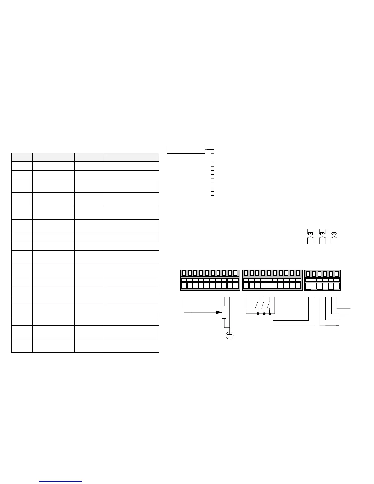
Terminal Name Purpose Comment
1 ANALOG INPUT 1 Setpoint 0V = 0%, 10V = 100%
2 ANALOG INPUT 2 Setpoint Trim 0V = 0%, 10V = 100%
3 ANALOG INPUT 3 Current Loop
Setpoint
0mA = 0%, 20mA = 100%
5 ANALOG INPUT 4 Torque Limit
Setpoint
0V = 0%, 10V = 150%
6 ANALOG OUTPUT 1 Ramp Output Absolute Speed Demand
0V = 0%, 10V = 100%
7 ANALOG OUTPUT 2 Load Output -10V = -150%,
10V = 150%
13 DIGITAL INPUT 1 Run 24V = Run
14 DIGITAL INPUT 2 Fast Stop 0V - Fast Stop
15 DIGITAL INPUT 3 Direction 0V = Forward, 24V =
Reverse
16 DIGITAL INPUT 4 External Trip 0V = Trip
(connect to terminal 18)
17 DIGITAL INPUT 5 Jog 24V = Jog
18 DIGITAL INPUT 6 Preset 1 Preset Speed Select
19 DIGITAL INPUT 7 Preset 2 Preset Speed Select
20 DIGITAL INPUT 8 Manual/Auto 0V = Manual Setpoint
24V = Auto Setpoint
21, 22 DIGITAL OUTPUT 1 Health Relay closed = drive healthy
23, 24 DIGITAL OUTPUT 2 Zero Speed Relay closed = drive at zero
speed
25, 26 DIGITAL OUTPUT 3 At Speed Relay closed = drive at
speed setpoint
HEALTH
Speed Setpoint
10
k
220V AC 3A maximum
TB1
TB3 TB4
into a resistive load (default)
12345678910
11 12 13 14 15 16 17 18 19 20
DOUT1_A
DOUT1_B
DOUT2_A
DOUT2_B
DOUT3_A
DOUT3_B
21 22 23 24 25 26
AIN1 (SPEED SETPOINT)
AIN2 (SETPOINT TRIM)
AIN3 (CURRENT LOOP)
0
V
AIN4 (TORQUE LIMIT)
AOUT1 (RAMP OUTPUT)
AOUT2 (LOAD OUTPUT)
+10V REF
0
V
-10V REF
+24VC
0V
DIN1 (RUN)
DIN2 (FAST STOP)
DIN3 (DIR)
DIN4 (EXT TRIP)
DIN5 (JOG)
DIN6 (PRESET 1)
DIN7 (PRESET 2)
DIN8 (MANUAL/AUTO)
ZERO SPEED
AT SPEED
General Wiring Diagram for Macro 99
The Operator Menu System for Macro 99
The default Operator menu system is shown below.
SETPOINT (REMOTE)
SPEED DEMAND
DRIVE FREQUENCY
MOTOR CURRENT
LOAD
DC LINK VOLTS
CURRENT LIMITING
PROCESS SETPOINT
STARTUP SCREEN
PROCESS FEEDBACK
PID ERROR
PID ENABLE
ENTER PASSWORD