Application Macros 15-4
605C Frequency Inverter
Macro 1: Basic Speed Control (default)
This macro provides standard control of the inverter.
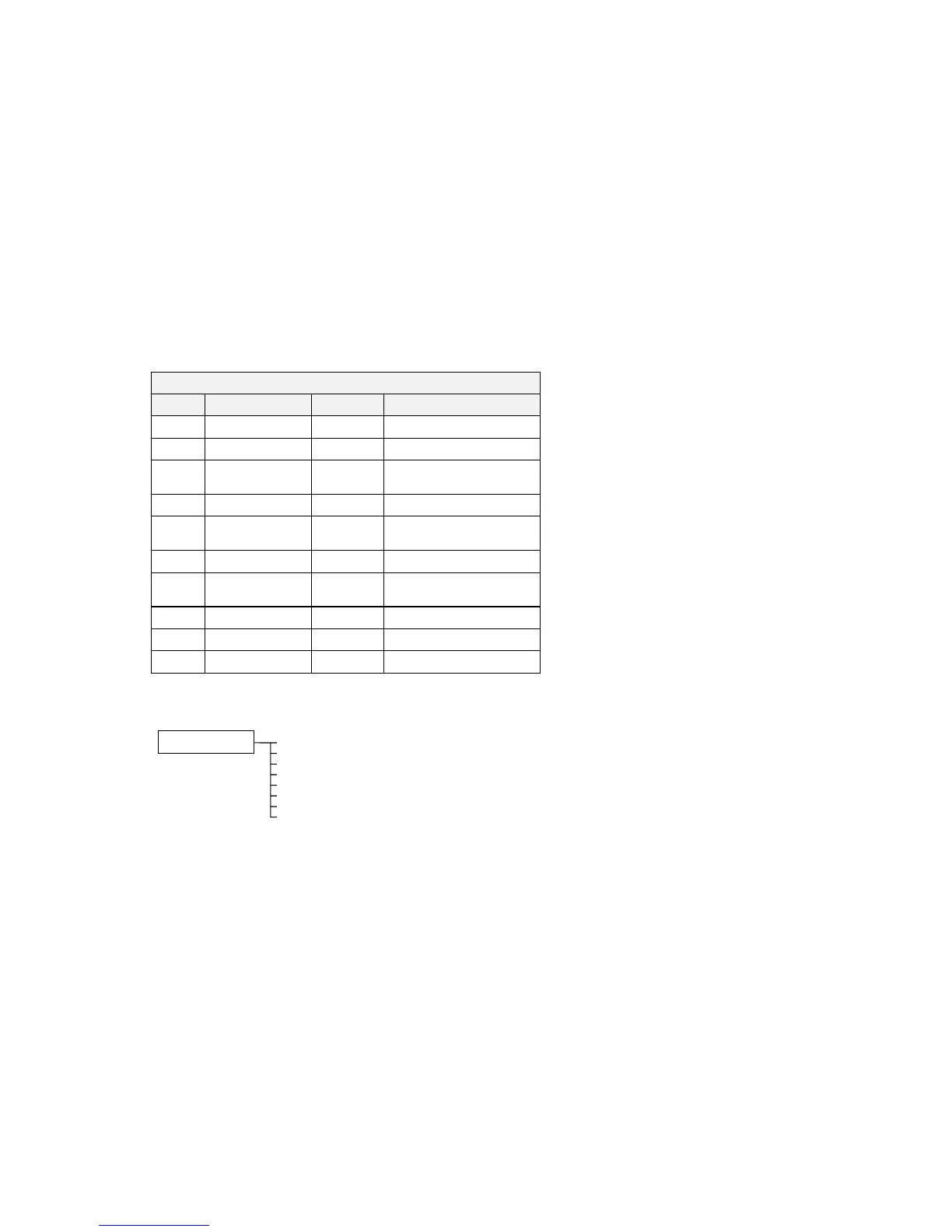
Control Wiring I/O
Terminal Name Purpose Comment
1 ANALOG INPUT 1 Setpoint 0V = 0%, 10V = 100%
2 ANALOG INPUT 2 Setpoint Trim 0V = 0%, 10V = 100%
6 ANALOG OUTPUT 1 Ramp Output Absolute Speed Demand
0V = 0%, 10V = 100%
13 DIGITAL INPUT 1 Run 24V = Run
14 DIGITAL INPUT 2 Trip Reset 0V to 24V transition
to reset trips.
15 DIGITAL INPUT 3 Direction 0V = Forward, 24V = Reverse
16 DIGITAL INPUT 4 External Trip 0V = Trip
(connect to terminal 18)
17 DIGITAL INPUT 5 Jog 24V = Jog
21, 22 DIGITAL OUTPUT 1 Health 0V = Tripped, i.e. not healthy
23, 24 DIGITAL OUTPUT 2 Running 0V = Stopped, 24V = Running
The Operator Menu System for Macro 1
The default Operator menu system is shown below.
SETPOINT (REMOTE)
SPEED DEMAND
DRIVE FREQUENCY
MOTOR CURRENT
LOAD
DC LINK VOLTS
CURRENT LIMITING
ENTER PASSWORD
STARTUP SCREEN