Application Macros 15-8
605C Frequency Inverter
Macro 3: Raise/Lower Trim
This macro provides a raise/lower (push button) interface for an additional Setpoint Trim. The Setpoint is
derived from the sum of ANALOG INPUT 1, ANALOG INPUT 2 and the output of the raise/lower ramp.
This ramp is controlled by the 3 digital inputs RAISE INPUT, LOWER INPUT and RESET of the
RAISE/LOWER function block.
The raise/lower trim is restricted to be +/- 10.00%. This limit is set by the MIN VALUE and MAX VALUE
parameters in the RAISE/LOWER function block.
Note that the raise/lower ramp output is automatically preserved in non-volatile memory during a
power-down
.
Terminal Name Purpose Comment
1 ANALOG INPUT 1 Setpoint 0V = 0%, 10V = 100%
2 ANALOG INPUT 2 Setpoint Trim 0V = 0%, 10V = 100%
6 ANALOG OUTPUT 1 Ramp Output Absolute Speed Demand,
0V = 0%, 10V = 100%
13 DIGITAL INPUT 1 Run 24V = Run
14 DIGITAL INPUT 2 Raise 24V = Ramp Up
15 DIGITAL INPUT 3 Lower 24V = Ramp Down
16 DIGITAL INPUT 4 External Trip 0V = Trip
(connect to terminal 18)
17 DIGITAL INPUT 5 Reset 24V = Reset and Hold Raise
Lower
21, 22 DIGITAL OUTPUT 1 Health 0V = Tripped, i.e. not healthy
23, 24 DIGITAL OUTPUT 2 Running 0V = Stopped, 24V = Running
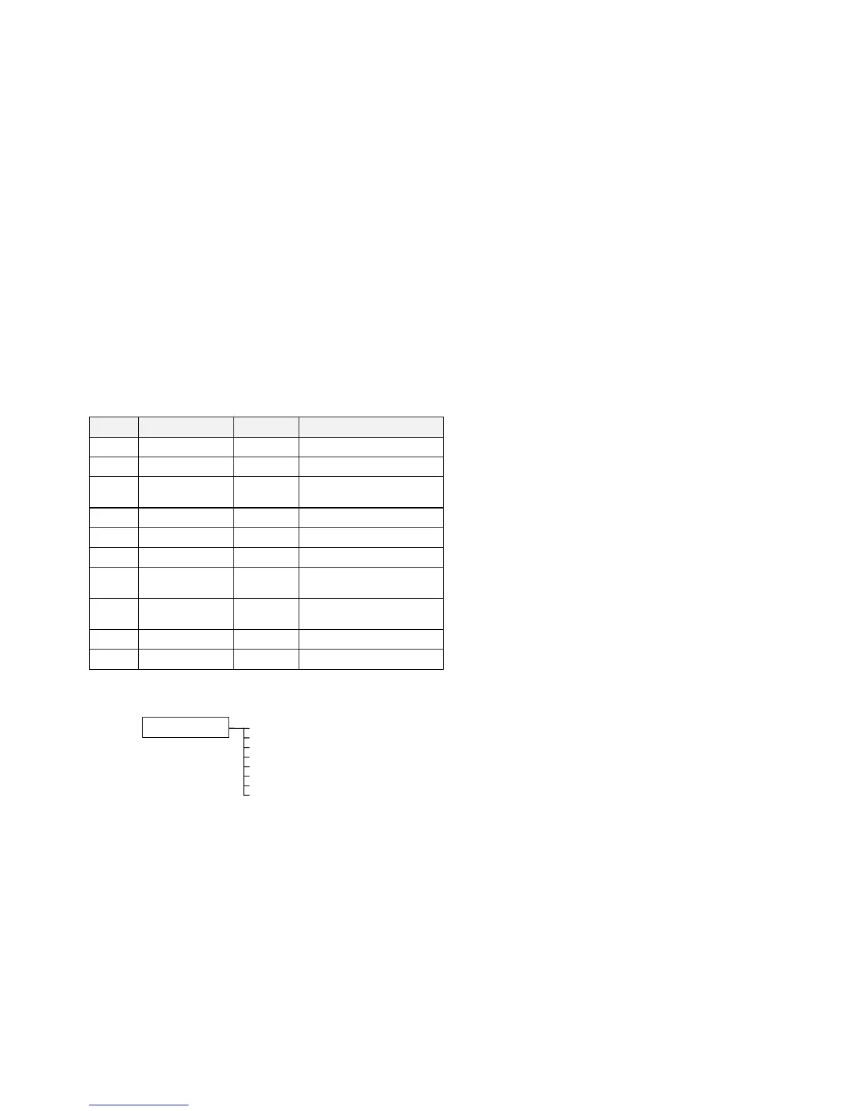
The Operator Menu System for Macro 3
The default Operator menu system is shown below.
SETPOINT (REMOTE)
SPEED DEMAND
DRIVE FREQUENCY
MOTOR CURRENT
LOAD
DC LINK VOLTS
CURRENT LIMITING
ENTER PASSWORD
STARTUP SCREEN