Installing the Inverter 3-5
605C Frequency Inverter
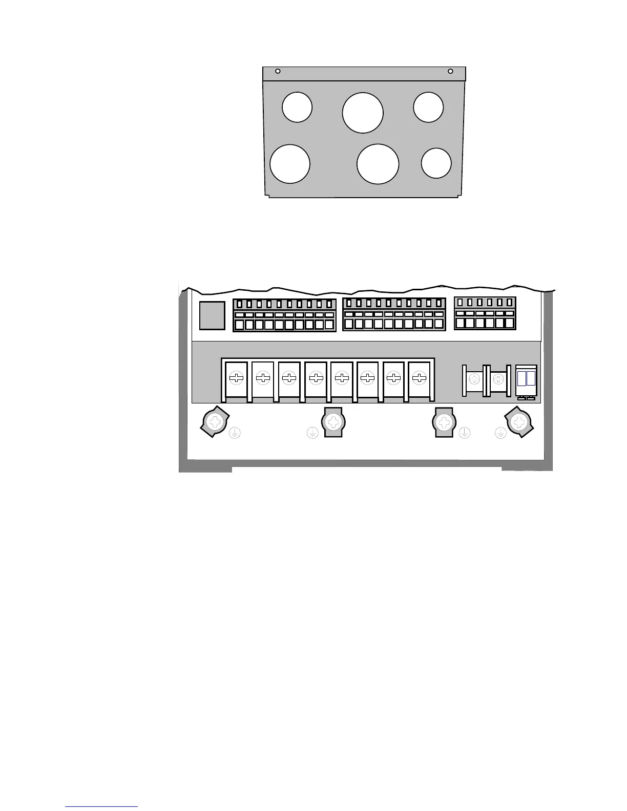
DBR+
DBR-
MOT/TEMP
Power Board
REM OP STA 1 2 3 4 5 6 7 8 9 10 11 12 13 14 15 16 17 18 19 20 21 22 23 24 25 26
L1
L2
L3
DC+ DC- M1/U M2/V M3/W
P3
TB3TB1
TB4
Figure 3-7 605C Inverter showing Earth, Power and Control Board Terminals
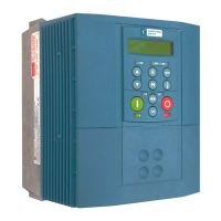
3 x 28.6mm diameter, 3 x 22.8mm diameter
power
supply
control
motor
Figure 3-6 Cable and Screen Fixings showing recommended usage of Gland Plate