6-10 Programming Your Application
605C Frequency Inverter
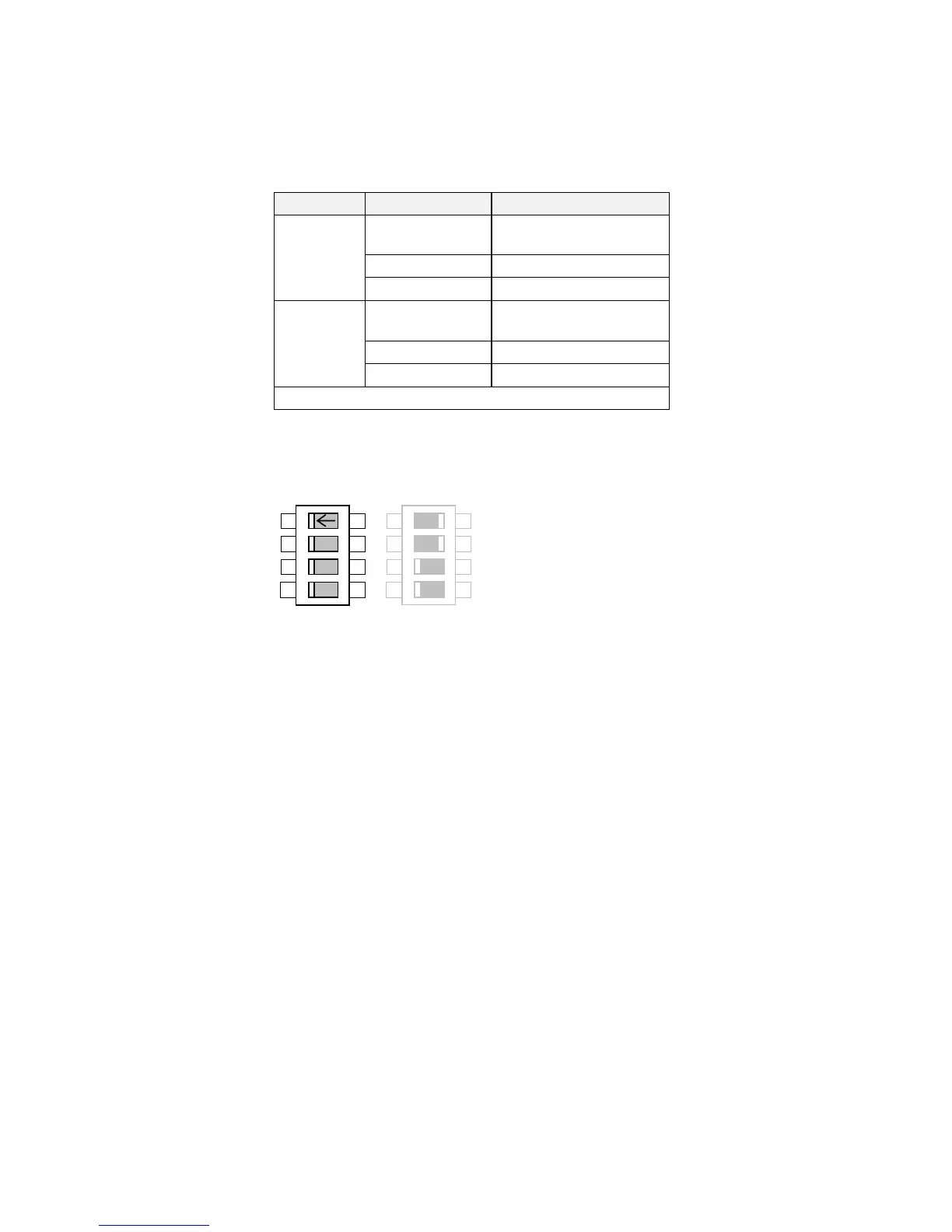
Configuration Switch Settings (SW1)
The analog input terminals are configured for voltage or current operation by the I/O
configuration switch settings. Remember to select the appropriate TYPE parameter.
Figure 6-3 I/O Configuration Switches shown at Manufacturing Defaults
Table 6-2 Select Input Signal
Input Type Switch Settings
ANALOG
INPUT
1
0-20 or 4-20mA SW1/1 OFF, SW1/2 ON
Terminal 1 0-10V* SW1/1 OFF, SW1/2 OFF*
± 10V
SW1/1 ON, SW1/2 OFF
ANALOG
INPUT
2
0-20 or 4-20mA SW1/3 OFF, SW1/4 ON
Terminal 2 0-10V* SW1/3 OFF, SW1/4 OFF*
± 10V
SW1/3 ON, SW1/4 OFF
* Default settings, as shown
SW1
4
3
2
1
ON
OFF
SW2
4
3
2
1
ON
OFF