6-12 Programming Your Application
605C Frequency Inverter
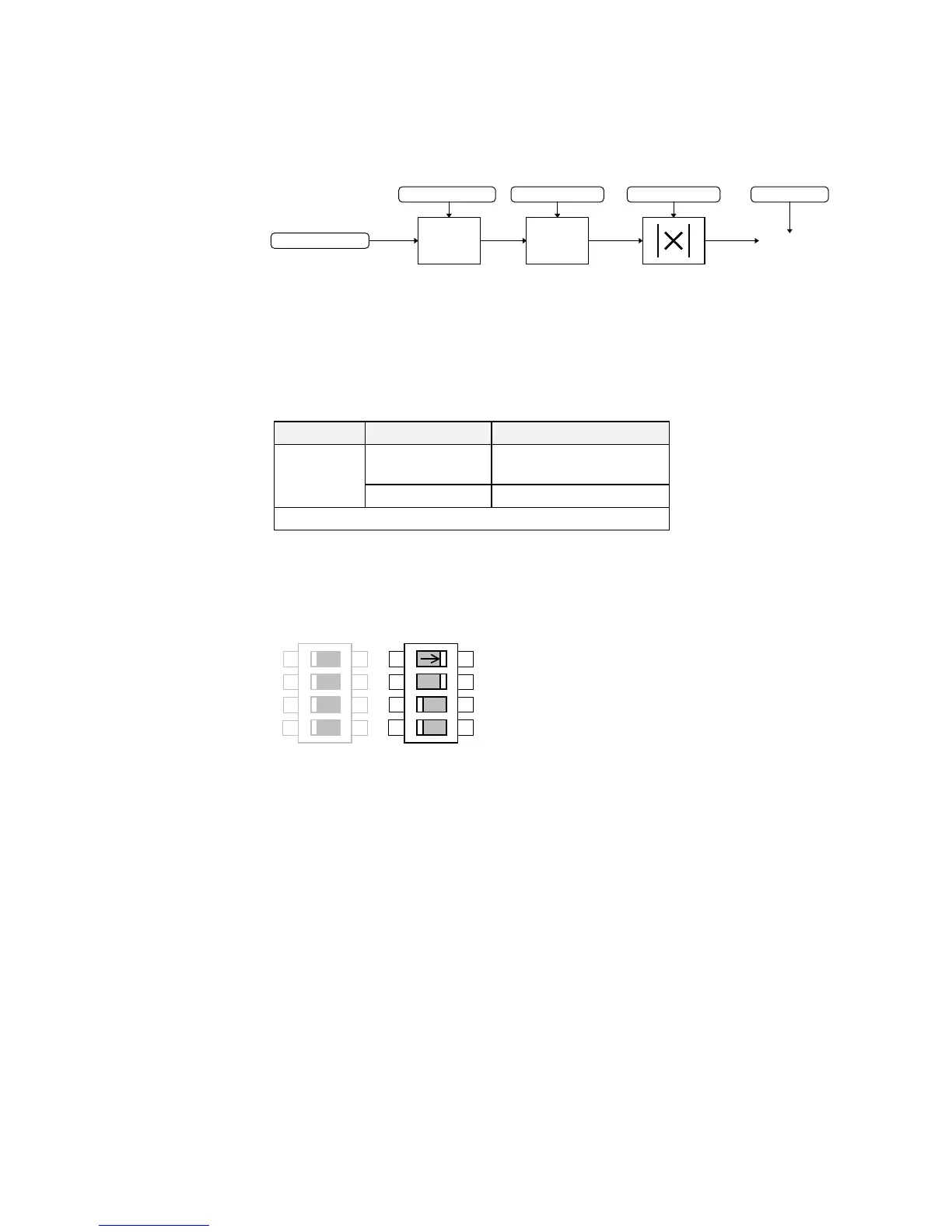
With scale and offset applied, a value of 0.00 causes the output to be equal to the low hardware
range, (i.e. 0V on ANALOG OUTPUT 1 or -10V on ANALOG OUTPUT 2 for the 0 to 10V
range ), a value of 100.00% causes the output to be equal to the high hardware range, (i.e. 10V
on the 0 to 10V range).
Configuration Switch Settings (SW2)
The analog output terminals are configured for voltage or current operation by the I/O
configuration switch settings. Remember to select the appropriate TYPE parameter.
Table 6-3 Select Input Signal
Figure 6-4 I/O Configuration Switches shown at Manufacturing defaults
X
FFSET
VALUE
ABS TYPE
Input Type Switch Settings
ANALOG
OUTPUT
1
0-20 or 4-20mA SW2/1 OFF, SW2/2 OFF
Terminal 6 0-10V* SW2/1 ON, SW2/2 ON*
* Default settings, as shown
SW1
4
3
2
1
ON
OFF
SW2
4
3
2
1
ON
OFF