Advanced control timer (TIM1) UM0306
162/519
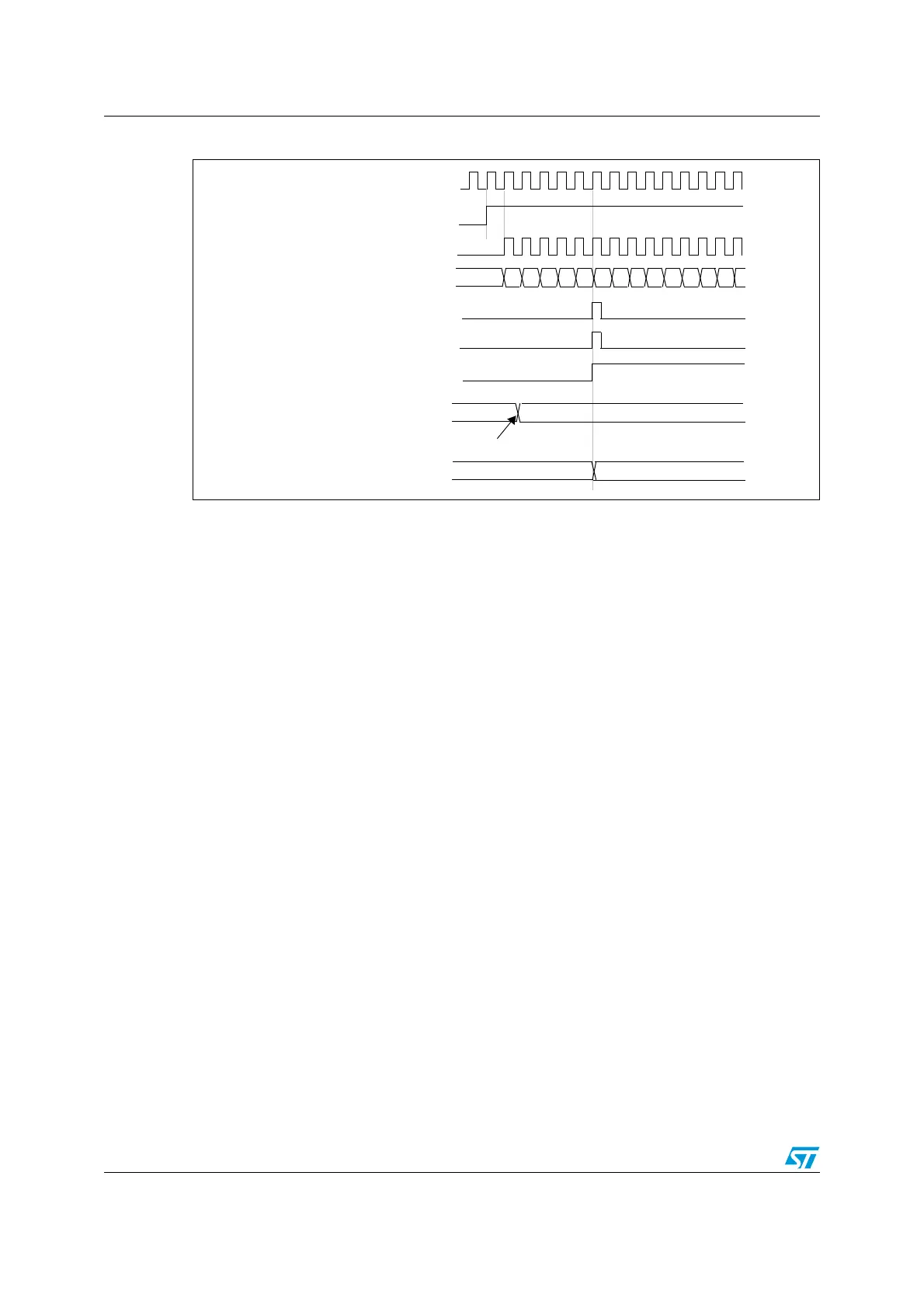
Figure 43. Counter timing diagram, Update event with ARPE=1 (counter overflow)
12.4.3 Repetition down-counter
Section 12.4.1: Time base unit describes how the update event (UEV) is generated with
respect to the counter overflows/underflows. It is actually generated only when the repetition
down-counter has reached zero. This can be useful when generating PWM signals.
This means that data are transferred from the preload registers to the shadow registers
(TIM1_ARR auto-reload register, TIM1_PSC prescaler register, but also TIM1_CCRx
capture/compare registers in compare mode) every N counter overflows or underflows,
where N is the value in the TIM1_RCR repetition counter register.
The repetition down-counter is decremented:
● At each counter overflow in up-counting mode,
● At each counter underflow in down-counting mode,
● At each counter overflow and at each counter underflow in center-aligned mode.
Although this limits the maximum number of repetition to 128 PWM cycles, it makes it
possible to update the duty cycle twice per PWM period. When refreshing compare
registers only once per PWM period in center-aligned mode, maximum resolution is
2xT
ck
, due to the symmetry of the pattern.
The repetition down-counter is an auto-reload type; the repetition rate is maintained as
defined by the TIM1_RCR register value (refer to Figure 44). When the update event is
generated by software (by setting the UG bit in TIM1_EGR register) or by hardware through
the slave mode controller, it occurs immediately whatever the value of the repetition down-
counter is and the repetition down-counter is reloaded with the content of the TIM1_RCR
register.
CK_PSC
36
CNT_EN
TIMER CLOCK = CK_CNT
COUNTER REGISTER
UPDATE INTERRUPT FLAG (UIF)
COUNTER OVERFLOW
UPDATE EVENT (UEV)
35 34 33 32 31 30 2FF8 F9 FA FB FCF7
AUTO-RELOAD PRELOAD REGISTER
FD 36
Write a new value in TIM1_ARR
AUTO-RELOAD ACTIVE REGISTER
FD 36

 Loading...


