Controller area network (bxCAN) UM0306
284/519
14.3.5 Receive FIFO
Two receive FIFOs are used by hardware to store the incoming messages. Three complete
messages can be stored in each FIFO. The FIFOs are managed completely by hardware.
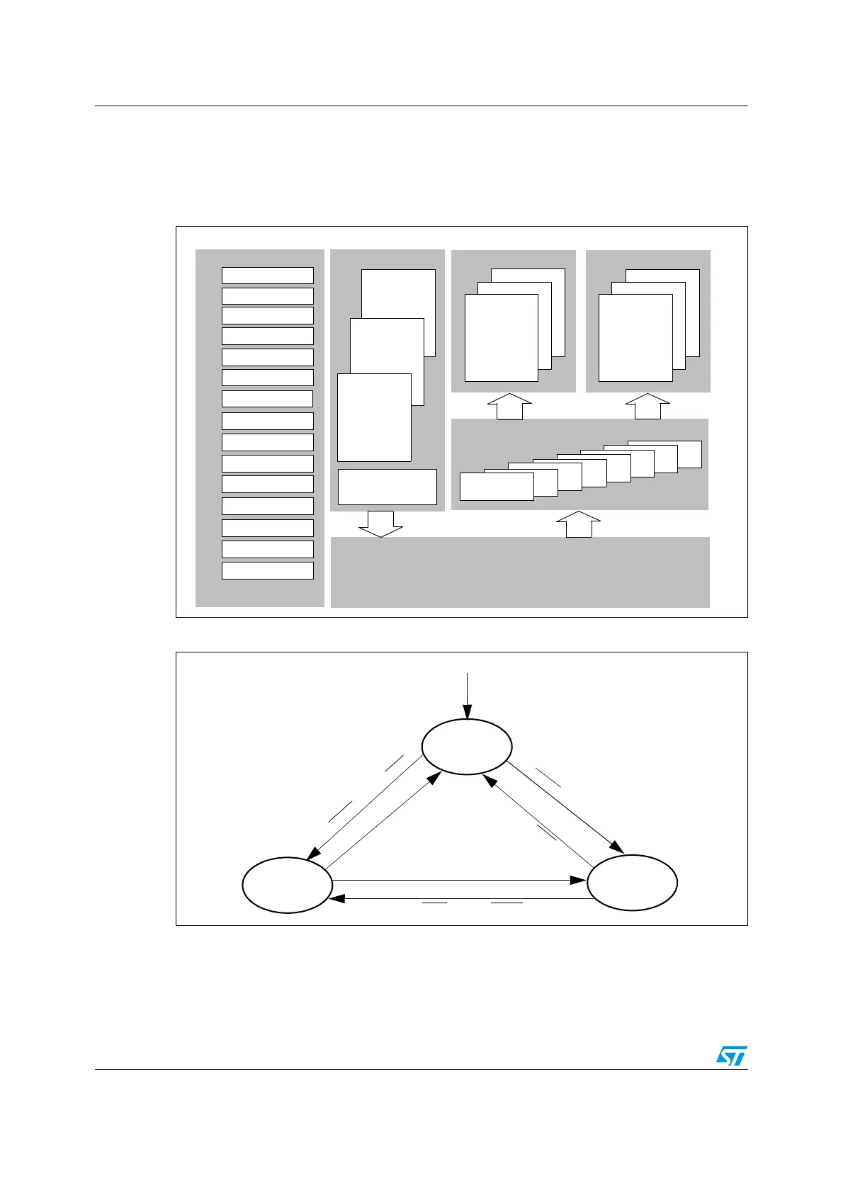
Figure 119. CAN block diagram
Figure 120. bxCAN operating modes
Note: 1 ACK = The wait state during which hardware confirms a request by setting the INAK or
SLAK bits in the CAN_MSR register
2 SYNC = The state during which bxCAN waits until the CAN bus is idle, meaning 11
consecutive recessive bits have been monitored on CANRX
Mailbox 2
Mailbox 1
12
..
CAN 2.0B Active Core
Mailbox 0
Transmission
Acceptance Filters
Tx Mailboxes
Master Control
Scheduler
Master Status
Transmit Control
Transmit Status
Transmit Priority
Receive FIFO
Error Status
Error Int. Enable
Tx Error Counter
Rx Error Counter
Diagnostic
Bit Timing
Filter Mode
Filter Config.
Interrupt Enable
Mailbox 0
1
2
Receive FIFO 1
..
3
2
1
Filter
0
Mailbox 0
1
2
Receive FIFO 0
Control/Status/Configuration
13
SLEEP
INITIALIZATION
NORMAL
RESET
SLAK= 1
INAK = 0
SLAK= 0
INAK = 1
SLAK= 0
INAK = 0
S
L
E
E
P
.
IN
R
Q
.
A
C
K
S
L
E
E
P
.
I
N
R
Q
.
A
C
K
INRQ . ACK
INRQ
. SYNC . SLEEP
S
L
E
E
P
.
A
C
K
S
L
E
E
P
.
S
Y
N
C
.
I
N
R
Q

 Loading...


