UM0306 Advanced control timer (TIM1)
189/519
Slave mode: Trigger mode
The counter can start in response to an event on a selected input.
In the following example, the up-counter starts in response to a rising edge on TI2 input:
● Configure the channel 2 to detect rising edges on TI2. Configure the input filter duration
(in this example, we don’t need any filter, so we keep IC2F=0000). The capture
prescaler is not used for triggering, so you don’t need to configure it. The CC2S bits are
configured to select the input capture source only, CC2S=01 in TIM1_CCMR1 register.
Write CC2P=1 in TIM1_CCER register to validate the polarity (and detect low level
only).
● Configure the timer in trigger mode by writing SMS=110 in TIM1_SMCR register.
Select TI2 as the input source by writing TS=110 in TIM1_SMCR register.
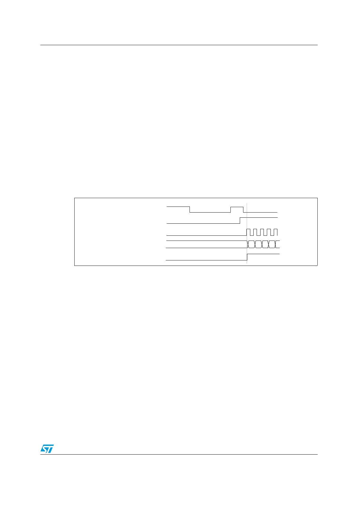
When a rising edge occurs on TI2, the counter starts counting on the internal clock and the
TIF flag is set.
The delay between the rising edge on TI2 and the actual start of the counter is due to the
resynchronization circuit on TI2 input.
Figure 70. Control circuit in trigger mode
Slave mode: External Clock mode 2 + trigger mode
The external clock mode 2 can be used in addition to another slave mode (except external
clock mode 1 and encoder mode). In this case, the ETR signal is used as external clock
input, and another input can be selected as trigger input (in reset mode, gated mode or
trigger mode). It is recommended not to select ETR as TRGI through the TS bits of
TIM1_SMCR register.
In the following example, the up-counter is incremented at each rising edge of the ETR
signal as soon as a rising edge of TI1 occurs:
COUNTER CLOCK = ck_cnt = ck_psc
COUNTER REGISTER
35 36 37 3834
TI2
cnt_en
TIF

 Loading...


