Reset and clock control (RCC) UM0306
52/519
programmed in alternate function mode. One of 4 clock signals can be selected as the MCO
clock.
● SYSCLK
● HSI
● HSE
● PLL clock divided by 2
The selection is controlled by the MCO[2:0] bits of the Clock configuration register
(RCC_CFGR).
4.3 RCC register description
Refer to Section 1.1 on page 23 for a list of abbreviations used in register descriptions.
4.3.1 Clock control register (RCC_CR)
Address offset: 00h
Reset value: 0000 0083h
Access: no wait state, word, half-word and byte access
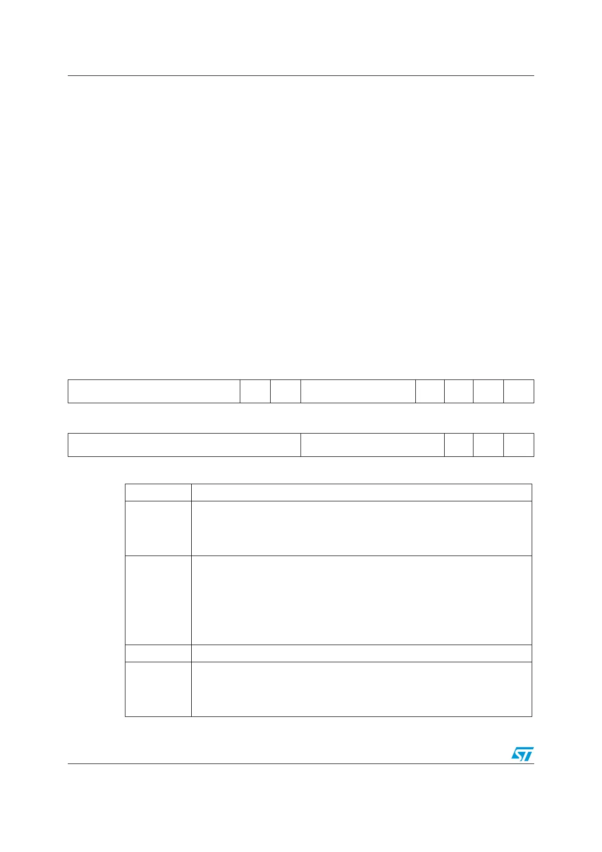
31 30 29 28 27 26 25 24 23 22 21 20 19 18 17 16
Reserved
PLL
RDY
PLLON Reserved
CSS
ON
HSE
BYP
HSE
RDY
HSE
ON
rrw rwrwrrw
1514131211109 87654321 0
HSI CAL[7:0] HSI TRIM[4:0] Res.
HSI
RDY
HSION
rrrrrrr rrwrwrwrwrw rrw
Bits 31:26 Reserved, always read as 0.
Bit 25
PLLRDY PLL clock ready flag
Set by hardware to indicate that the PLL is locked.
0: PLL unlocked
1: PLL locked
Bit 24
PLLON PLL enable
Set and reset by software to enable PLL.
Reset by hardware when entering STOP and STANDBY mode. This bit can not
be reset if the PLL clock is used as system clock or is selected to become the
system clock.
0: PLL OFF
1: PLL ON
Bits 23:20 Reserved, always read as 0.
Bit 19
CSSON Clock Security System enable
Set and reset by software to enable clock detector.
0: Clock detector OFF
1: Clock detector ON if external 1-25 MHz oscillator is ready.

 Loading...


