UM0306 Inter-integrated circuit (I2C) interface
349/519
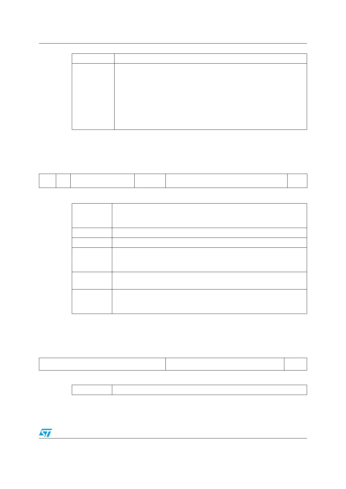
15.6.3 Own address register 1 (I2C_OAR1)
Reset Address offset: 08h
Value: 0000h
15.6.4 Own address register 2 (I2C_OAR2)
Address offset: 0Ch
Reset Value: 0000h
Bits 7:6 Reserved, forced by hardware to 0.
Bits 5:0
FREQ[5:0]: Peripheral Clock Frequency
Input clock frequency must be programmed to generate correct timings
The allowed range is between 2 MHz and 50 MHz
000000: Not allowed
000001: Not allowed
000010: 2 MHz
...
110010: 50 MHz
Higher than 110010: Not allowed
15141312111098 7 654321 0
ADD
MODE
Res. Reserved ADD[9:8] ADD[7:1] ADD0
rw rw rw rw rw rw rw rw rw rw rw rw
Bit 15
ADDMODE Addressing Mode (Slave mode)
0: 7-bit slave address (10-bit address not acknowledged)
1: 10-bit slave address (7-bit address not acknowledged)
Bit 14 Must be configured and kept at 1.
Bits 13:10 Reserved, forced by hardware to 0.
Bits 9:8
ADD[9:8]: Interface Address
7-bit addressing mode: don’t care
10-bit addressing mode: bits9:8 of address
Bits 7:1
ADD[7:1]: Interface Address
bits 7:1 of address
Bit 0
ADD0: Interface Address
7-bit addressing mode: don’t care
10-bit addressing mode: bit 0 of address
151413121110987 654321 0
Reserved ADD2[7:1] ENDUAL
rw rw rw rw rw rw rw rw
Bits 15:8 Reserved, forced by hardware to 0.

 Loading...


