EN-12
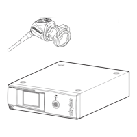
Setting Up the Console
Refer to the instructions below and the wiring diagram on the following page
for a typical 1488HD conguration.
1. Connect the console’s AC power to a hospital-grade outlet.
2. Connect one of the console’s DVI outputs to an available DVI input on a
Stryker digital capture console such as the SDC3.
• The 1488HD console can also be connected to additional SDC video
inputs or directly to one or more display monitors; the rear panel
provides one analog and two digital-video outputs (or three with
1488010001):
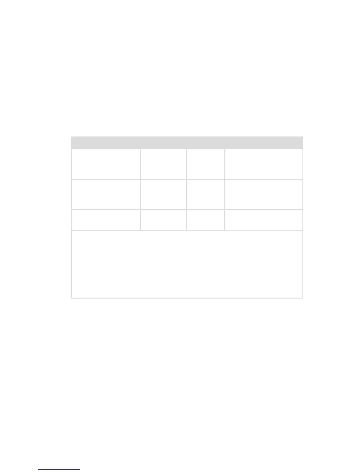
Output Type Output Cable Connector
Analog S-VHS 1* S-VHS 4 pin Mini-Din
(push-only
connectors)
Digital (standard) DVI-I1** and
DVI-I2**
DVI 29 pin (push-only
connectors, with two
tightening knobs)
Digital (optional in
1488010001)
DVI over
optical Fiber
Fiber (×4) Lucent connector
ber (×4) (push only)
* On some monitors, S-VHS inputs may be labeled Y/C.
** The DVI connectors can also output analog SXGA signals through a
DVI-I to VGA adapter.
When using any device with unterminated analog video inputs,
connect a cable from the VIDEO OUT of that device to the VIDEO IN on
the monitor.
3. Connect the DVI output from the Stryker digital capture console to the
DVI input on the display monitor.
4. Using the provided remote cables, connect remote outputs 1 and 2 from
the 1488HD console to a Stryker digital capture console. (The remote
inputs should be connected to the same channel as the video input.)
• Devices connected to the remote outputs can be operated using the
console touchscreen or the P button on the camera head. See the
“Operation” section for details.
5. Connect a USB A-to-B cable (also available from Stryker, part 0105187988)
from the console’s Light Source output to the SIDNE input on the Stryker
L9000 Light Source.
• The 1488 HD camera head can be programmed to toggle “Run/
Standby” controls on the L9000. Contact a Stryker representative for
more information about enabling this advanced feature.
 Loading...