EN-16
Connecting the DVI Fiber Outputs
Using adjustments or performing procedures dierently than
specied below may result in hazardous radiation exposure.
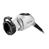
The 1488 HD Camera has the optional upgrade, the ber output, for model
1488010001. This upgrade contains four laser diodes to transmit a DVI output
over beroptic cables.
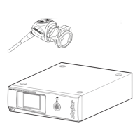
1. Connect four individual bers (terminated in Lucent connectors) to the
red (R), green (G), blue (B) and clock (C) laser diodes on the console rear
panel.
2. Connect the four bers to a compatible beroptic DVI receiver.
• The four bers should be connected to the camera console in the
labeled order: RGBC
• The bers should be connected to the monitor in one of two
congurations: CBGR (reverse order) or BGRC (R/B switched).
Note: The 1488 HD Camera model 1488010001 is a Class 1 laser product per
IEC60825-1 and 21CFR1040.
 Loading...