Return To Table of Contents
30 2030-809-002 REV D www.stryker.com
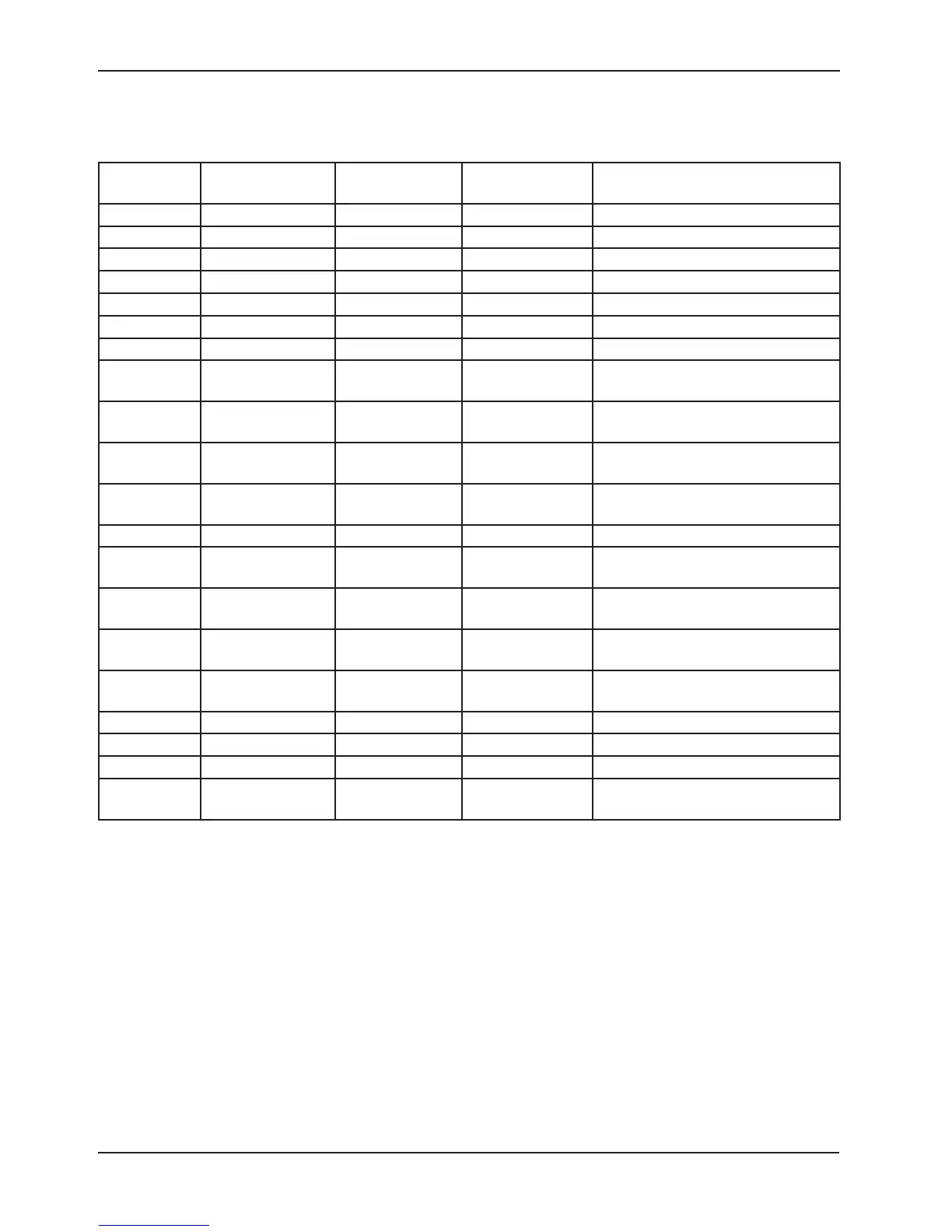
Electrical System Information
CABLE
LOCATION
VOLTAGE POSITIVE LED NEGATIVE LED DESCRIPTION
W +12 VDC Pin 1 Pin 4 or 5 Relays & Siderails Light Voltage
W +5 VDC Pin 2 & 3 Pin 4 or 5 +5 VDC from Power Supply
W -12 VDC Pin 6 Pin 4 or 5 Relays & Siderails Light Voltage
J +5 VDC Pin 4 (Green) Pin 2 (Black) +5 VDC for Head Lift Pot
J 0 - 5 VDC Pin 3 (Red) Pin 2 (Black) Head Lift Pot Wiper
C +5 VDC Pin 1 (Blue) Pin 2 (White) +5 VDC for Foot Lift Pot
C 0 - 5 VDC Pin 3 (Black) Pin 2 (White) Foot Lift Pot Wiper
GG 0 VAC W/O Switch
120 VAC W/Switch
Pin 1 (Black) Pin 3 (White) Fowler Up
GG 0 VAC W/O Switch
120 VAC W/Switch
Pin 2 (Red) Pin 3 (White) Fowler Down
CC 0 VAC W/O Switch
120 VAC W/Switch
Pin 2 (Black) Pin 1 (White) Gatch Up
CC 0 VAC W/O Switch
120 VAC W/Switch
Pin 3 (Red) Pin 1 (White) Gatch Down
O 110 VAC Pin 1 Pin 2 Line Voltage to Bed
N 0 VAC W/O Switch
120 VAC W/Switch
Pin 3 (Black) Pin 1 (White) Head Lift Down
N 0 VAC W/O Switch
120 VAC W/Switch
Pin 6 (Red) Pin 1 (White) Head Lift Up
G 0 VAC W/O Switch
120 VAC W/Switch
Pin 3 (Black) Pin 1 (White) Foot Lift Down
G 0 VAC W/O Switch
120 VAC W/Switch
Pin 6 (Red) Pin 1 (White) Foot Lift Up
ZZ +5 VDC Pin 1 (Red) Pin 4 (Black) +5 VDC for Fowler Pot
ZZ 1-5 VDC Pin 3 (Green) Pin 4 (Black) Fowler Pot Wiper
V 9 VDC Pin 2 (Red) Pin 1 (Black) Nurse Call Backup Battery
JJ 12 VDC when Bed
Exit is Alarming
Pin 1 (Red) Pin 2 (Black) Bed Exit Beeper
STANDARD CPU BOARD = 3002-407-950 / IAWARENESS CPU BOARD - 3003-407-900 (CONTINUED)