Product Description / Intended Use
15 EN
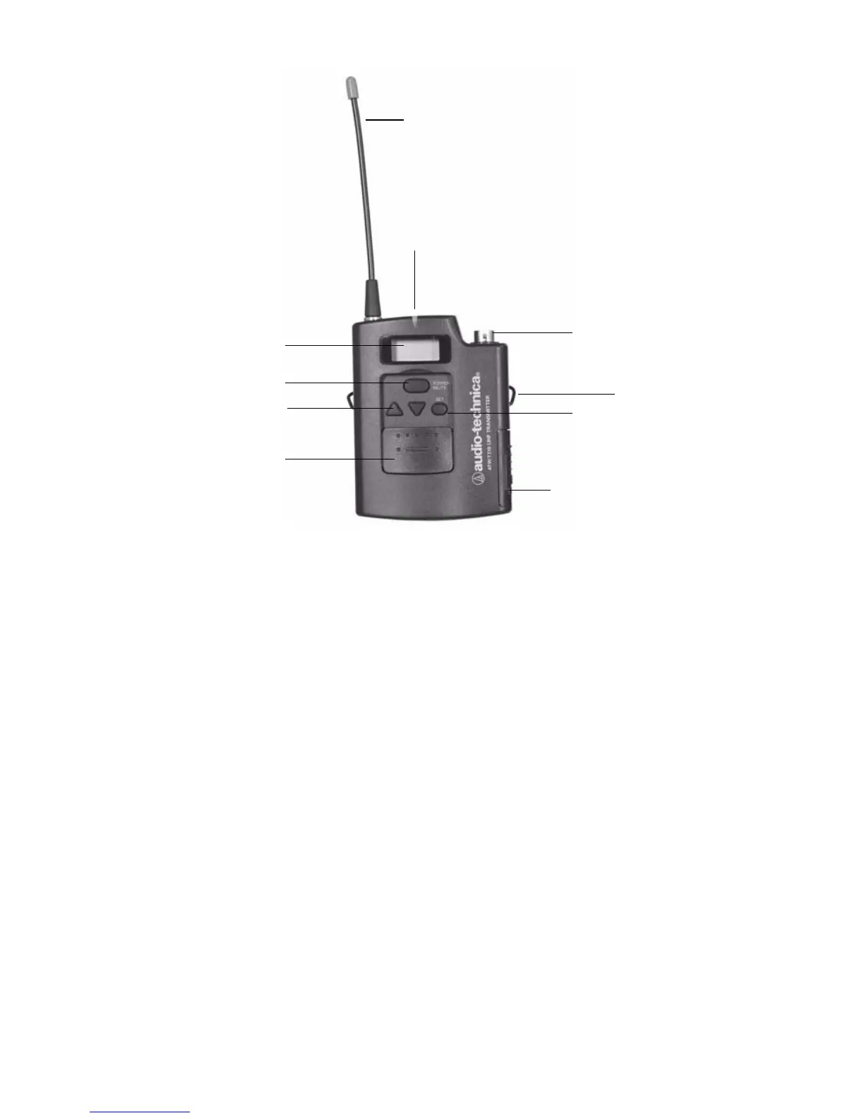
Figure 6: The transmitter
1. Antenna
2. Power-on LED: Shines red when the transmitter is powered on.
3. Audio Input Jack: Connects the transmitter to the headpiece
connector.
4. Mounting Clip: Clips to clothing for easy support.
5. Mode/Set Button: Accesses transmitter modes when pressed
once (repeated pressing advances through the different modes);
locks the mode setting when held for several seconds.
6. Battery Door: provides access to the transmitter batteries (2 AA
batteries).
7. Sliding Control Cover: protects the transmitter buttons from
inadvertent selections.
8. Up/Down Arrows: Scroll through various transmitter settings.
9. Power/Mute Button: Powers on the transmitter when held for 3
seconds; powers off the transmitter when held for another 3
seconds; when the transmitter is on, mutes RF signals when
pressed.
10. LCD Window: Displays transmitter options/status.
1
2
3
4
5
7
8
9
6
10