16 EN
Figure 7: The receiver, front panel
1. Power Switch: Powers the system on and off.
2. Alert Indicator: Shines red to indicate that the transmitter is in
the mute mode or is powered off, or to indicate system warnings,
such as weak transmitter battery, or no/poor RF communication
between the transmitter and receiver.
3. LCD Window: Indicates control settings and status readings.
4. Tuner Operator Indicator: Indicates which tuner (A or B) has
better reception and is in operation.
5. Up/Down Buttons: Advance through menus; select operating
frequency; edit receiver function choices.
6. Mode/Set Button: Works in conjunction with the up/down
buttons to step through menus, choose operating frequency, and
select function.
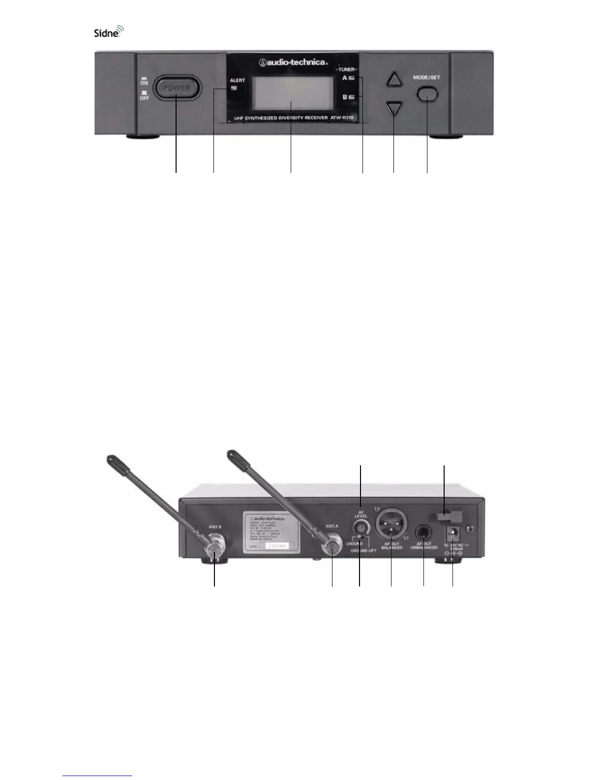
Figure 8: The receiver, rear panel
1. AF Level Control: Adjusts the audio output level of both AF
output jacks.
2. Cord Hook: Secures the DC power cord to the receiver to avoid
inadvertent disconnection.
3. Antenna Input Jack B: Connects to a provided antenna.
4. Antenna input Jack A: Connects to a provided antenna.
1
23
4
5
6
12
345678