19
Info
...Water/Temperature
...Air/Pressure
...Air/Humidity/more/more
© STULZ GmbH – all rights reserved EN/06.2019/G57
C7000 INSTRUCTIONS FOR A/C UNITS
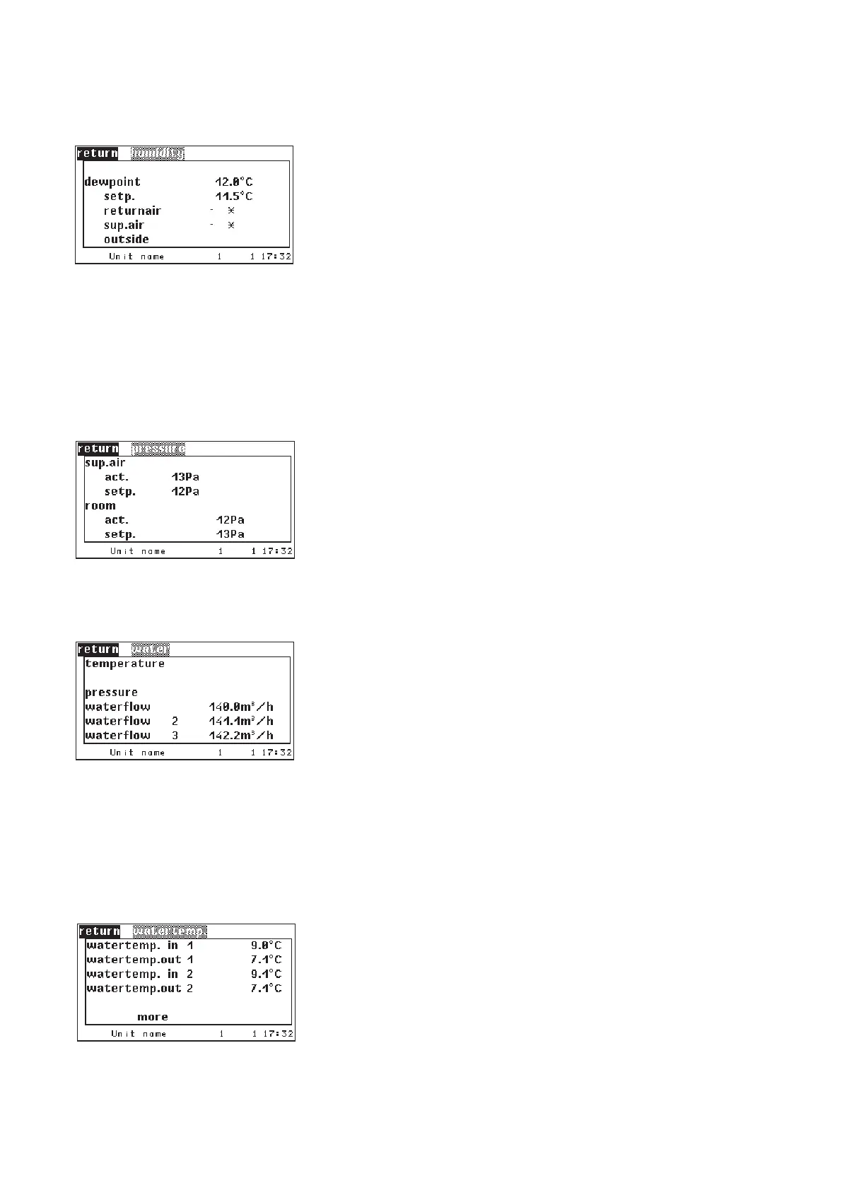
In this window the actual value and the setpoint for the differential pressure of
the supply air (pressure gain in contrast to the room air pressure) in the raised
floor or cold aisle compartment is indicated.
The actual value and the setpoint for the room air pressure, which are displayed
in the lower part, is measured as differential pressure between the room and
the external pressure.
(part of DFC² control)
1. actual dew point
2. dew point of the setpoints (temperature and humidity)
You find a detailed description in chapter 5.4.6 in the description of humidifi-
cation and dew point control.
Values
Here the measured values of the cooling water circuits 1 and 2 are displayed.
1. Water temperature at the inlet, circuit 1
2. Water temperature at the outlet, circuit 1
3. Water temperature at the inlet, circuit 2
4. Water temperature at the outlet, circuit 2
Further menu only relevant for the chiller.
To display the water volume flow the A/C unit must be equipped with volume
measuring device.
The water volume flow sensor must be configured with the sensor purpose „50
- water volume flow“.
To display the water volume flow for example in the second water circuit (in the
menu "waterflow 2") of a CW2 A/C unit the water volume flow sensor must be
configured with the sensor purpose „53 - water volume flow 2“.
To display a third water volume flow for example through the hot water reheat
(in the menu "waterflow 3") the water volume flow sensor must be configured
with the sensor purpose „54 - water volume flow 3“.
.../Water