51
➋
➌
➍
➎
➏
➌
➍
➎
➏
➊a
➊b
➊c
➊d
➊e
➊f
➊d ➊e
➊f
➊a ➊b
➊c
© STULZ GmbH – all rights reserved EN/06.2019/G57
C7000 INSTRUCTIONS fOR A/C UNITS
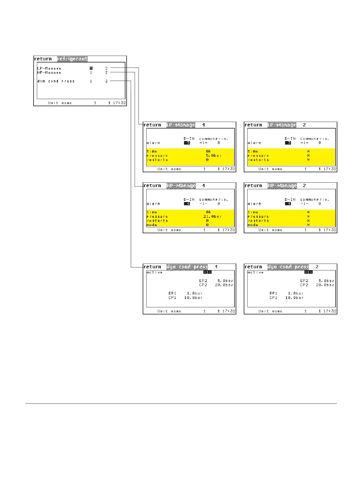
Config/Values/Refrigerant
In this menu you can configure the
low pressure alarm individually for
each refrigerant circuit.
The menu items for the LP man-
agement can not be used at the
time.
In this menu you can configure the
high pressure alarm individually for
each refrigerant circuit.
The menu items for the HP man-
agement can not be used at the
time.
A dynamic condensation pressure
control can be configured and acti-
vated for each refrigerant circuit in
the menus beside.
The graphical arrangement of the
parameter reflects the form of the
condensation pressure curve.
By the parameter in the first line you can activate the control.
➋
The curve is determined by the following four parameters:
EP1 - evaporation pressure 1
CP1 - condensation pressure 1
EP2 - evaporation pressure 2
CP2 - condensation pressure 2
digital input, common alarm release,
digital output to forward the alarm
digital input, common alarm release,
digital output to forward the alarm
lowpressure 1 din 2
lowpressure 1 commonalarm 1
lowpressure 1 alarmprio 7
highpressure 1 din 4
highpressure 1 commonalarm 1
highpressure 1 alarmprio 8
cpset 1 dyn 1
cpset 1 ep1 6,5
cpset 1 cp1 12,8
cpset 1 ep2 17,0
cpset 1 cp2 32,6