59
➊
➋
➌
➍
➎a
➎b
➏a
➏b
➐
➑a
➑b
➒a
➒b
➓
© STULZ GmbH – all rights reserved EN/06.2019/G57
C7000 INSTRUCTIONS fOR a/C UNITS
The corresponding commands:
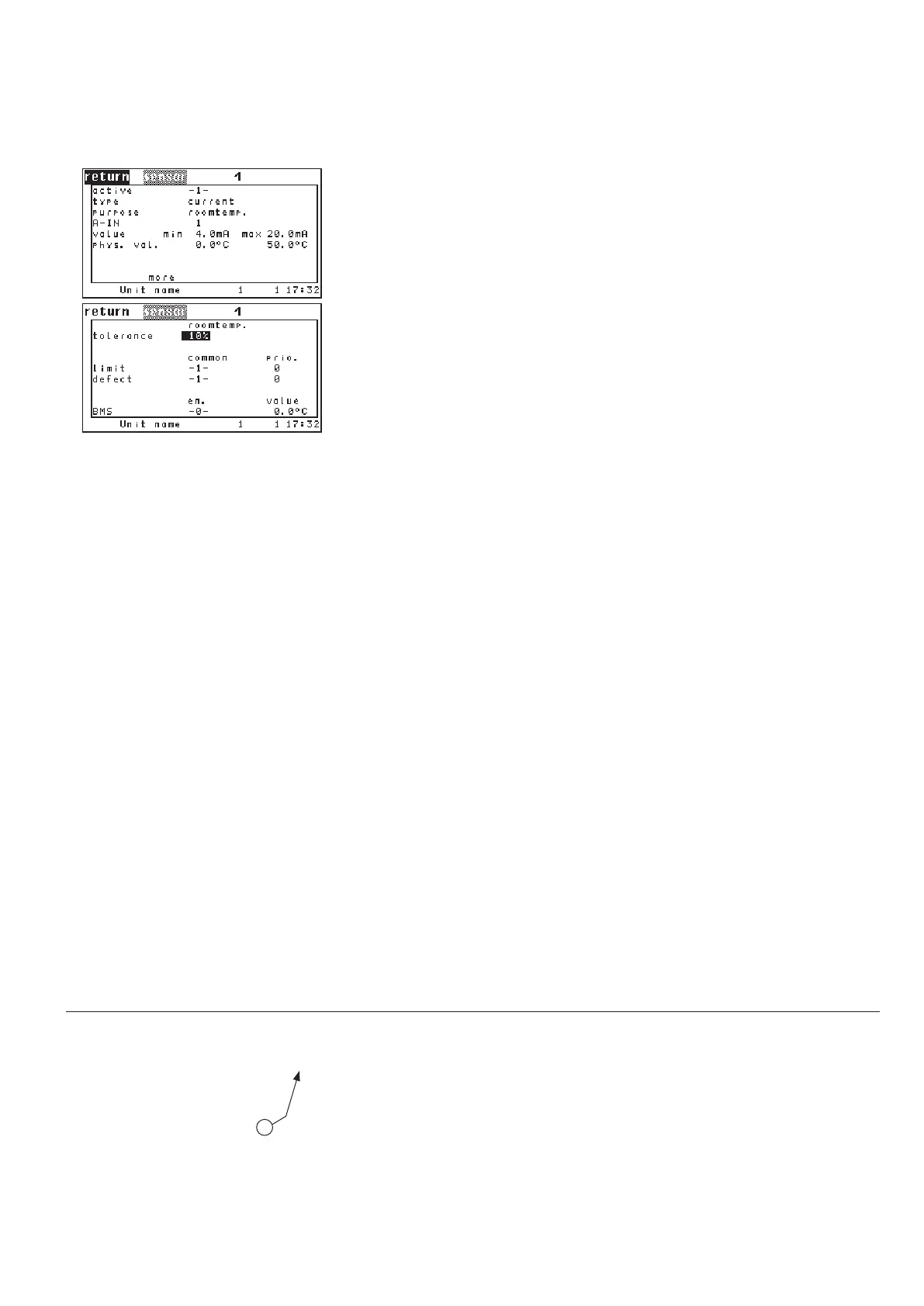
Components
Sensor/121
By setting the parameter "ACTIVE" on 1 you add a sensor to the configuration.
With "0" you disable the sensor.
➊
In the next line you determine the sensor type (current, voltage). ➋
With the parameter "PURPOSE" you specify for what the sensor is used ➌.
See left listing.
With the parameter "AIN" you adjust the analog input for the proportional sen-
sor signal.
➍
The following 5 items serve to calibrate the sensor. The minimum measure val-
ue (phys. value)
➏a is assigned to the minimum output (value). ➎a
The maximum measure value (phys. value) ➏b is assigned to the maximum out-
put (value).
➎b
The unit of the adjusted measure value depends on the sensor purpose (155).
The unit of the adjusted output depends on the sensor type (current, voltage).
If there is more than one sensor with the same purpose, an average value is
calculated. In the first line of the second menu you can adjust a maximum dif-
ference to the average value.
➐ If the maximum difference is exceeded, the
alarm "limit exceeded: Sensor ##" is released. For the evaluation of the sensor
excess alarm at least three sensors with the same purpose are needed.
Alarm parameters:
sensor excess alarm in the second line,
common alarm release
➑a.
alarm priority ➑b
sensor failure alarm in the third line,
common alarm release
➒a.
alarm priority ➒b.
In the last line it is indicated whether the measured value is provided by a BMS
(e.g. by an external sensor). If this is the case the value is automatically enabled
and accepted as actual value for this sensor. The value in column "EN" will be
-1- then. The measured value itself is displayed in the column "Value".
This external measuring value can be disabled by setting "0" for the parameter
in column "EN"
➓. Then the value, which is measured at the corresponding ana-
log input is taken as actual value.
PURPOSE:
1 - Room temperature
2 - Room humidity
3 - Supply temperature
4 - Supply humidity
5 - Water temperature, inlet 1
6 - Outside temperature
7 - Outside humidity
8 - Hotgas temperature 1
9 - Condensation pressure 1
10 - Suction gas temperature 1
11 - Evaporation pressure 1
12 - Water temperature, inlet 2
13 - Hotgas temperature 2
14 - Condensation pressure 2
15 - Suction gas temperature 2
16 - Evaporation pressure 2
17 - Setpoint temperature
18 - Setpoint humidity
19 - Water temperature, outlet 1
20 - Water temperature, outlet 2
21 - Water pressure
23 - Universal temperature 1
24 - Differential pressure 1
Sensor type:
1: Current
2: Voltage
see listing "Purpose"
continued overleaf
sensor 1 conf 1
sensor 1 type 3
sensor 1 use 5
sensor 1 ain 3
sensor 1 minout 0.0
sensor 1 maxout 9.0
sensor 1 minmeas -20.0
sensor 1 maxmeas 40.0
sensor 1 div 20
sensor 1 commonalarm 1
sensor 1 alarmprio 2
sensor 1 commonalarmbr 1
sensor 1 alarmpriobr 3
sensor 1 bms 0
Config