83
➊
➋
➌
➍
➊
➋
➌
➍
➎
© STULZ GmbH – all rights reserved EN/06.2019/G57
C7000 INSTRUCTIONS fOR a/C UNITS
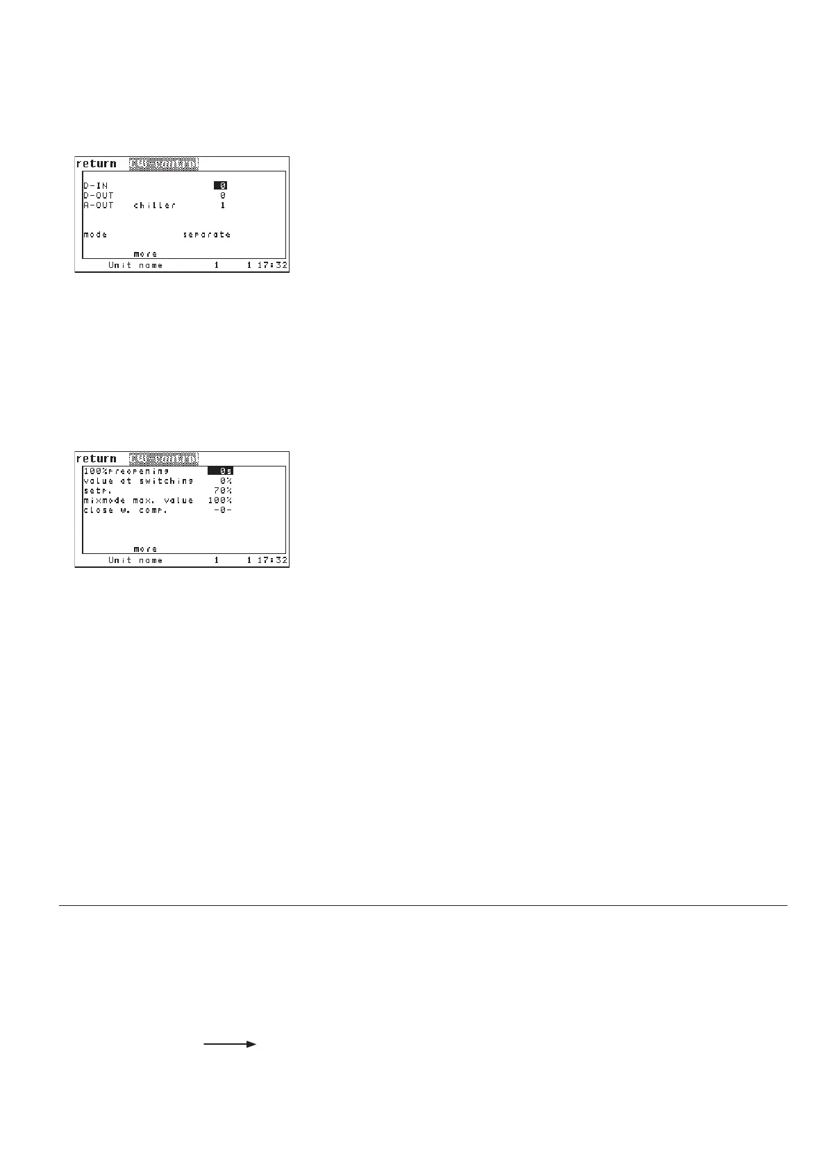
The corresponding commands:
Components/Cooling/Valves
CW-control
The digital input, which receives the signal for the commutation from valve 1 to
valve 2, can be assigned in the first line.
➊
(relevant only for A/C units type CW2)
In the second line you can set the digital output
➋ at which the actual state of
the changeover is output.
(relevant only for A/C units type CW2)
In the third line you can adjust the analog output
➌ for the chillersaver signal.
In the fourth line you can adjust the operating mode
➍ by which the valves of
CW2 units are controlled. (See chapter 6.4.)
In the first line you can set a time delay
➊ which must pass until the control of
the GE/CW valve begins and the water limit alarms are monitored. Until this
time has elapsed, the valve is fully (100%) opened.
The parameter in the second line is only important for CW2 units.
Here you can set an opening degree
➋ for the CW valve of the first water cir-
cuit. This opening degree is kept by the valve while the cooling is produced by
water circuit 2. By this, a minimum water flow is guaranteed in circuit 1, which
is necessary to measure the water temperature. With a sufficiently low water
temperature the cooling production can be switched back to circuit 1. Without
a cooling request in circuit 1 the valve is completely closed.
Following parameters are only relevant for A/C units type GE:
In the third line you can adjust a setpoint
➌ for the opening degree of the GE
valve. This parameter is relevant only for the DFC control. For this a separate
manual exists.
By the parameter in the fourth line
➍ you can define a maximum opening
degree for the GE valve. This value is only valid during mix mode and serves to
limit the water volume flow through the GE valve, so that a sufficient waterflow
runs through the G valve.
In the fifth line you can prevent mixed operation of free cooling and compressor
cooling by setting the "Close at comp" value
➎ to "1".
0: separate
1: added
2: DFC
3: DTC
CW-control .../more
cw 100 30
cw switchopen 10
cw opensp 70
cw maxmix 65
cw compoff 1
cw din 17
cw dout 9
cw savaout 5
cw oper 0
Config
.../more