88
➊
➋
➌
➍
➎
➏
➐
➊
➋
➌
➍
➎
➏
➐
➑
➒
EN/06.2019/G57 © STULZ GmbH – all rights reserved
C7000 INSTRUCTIONS fOR A/C UNITS
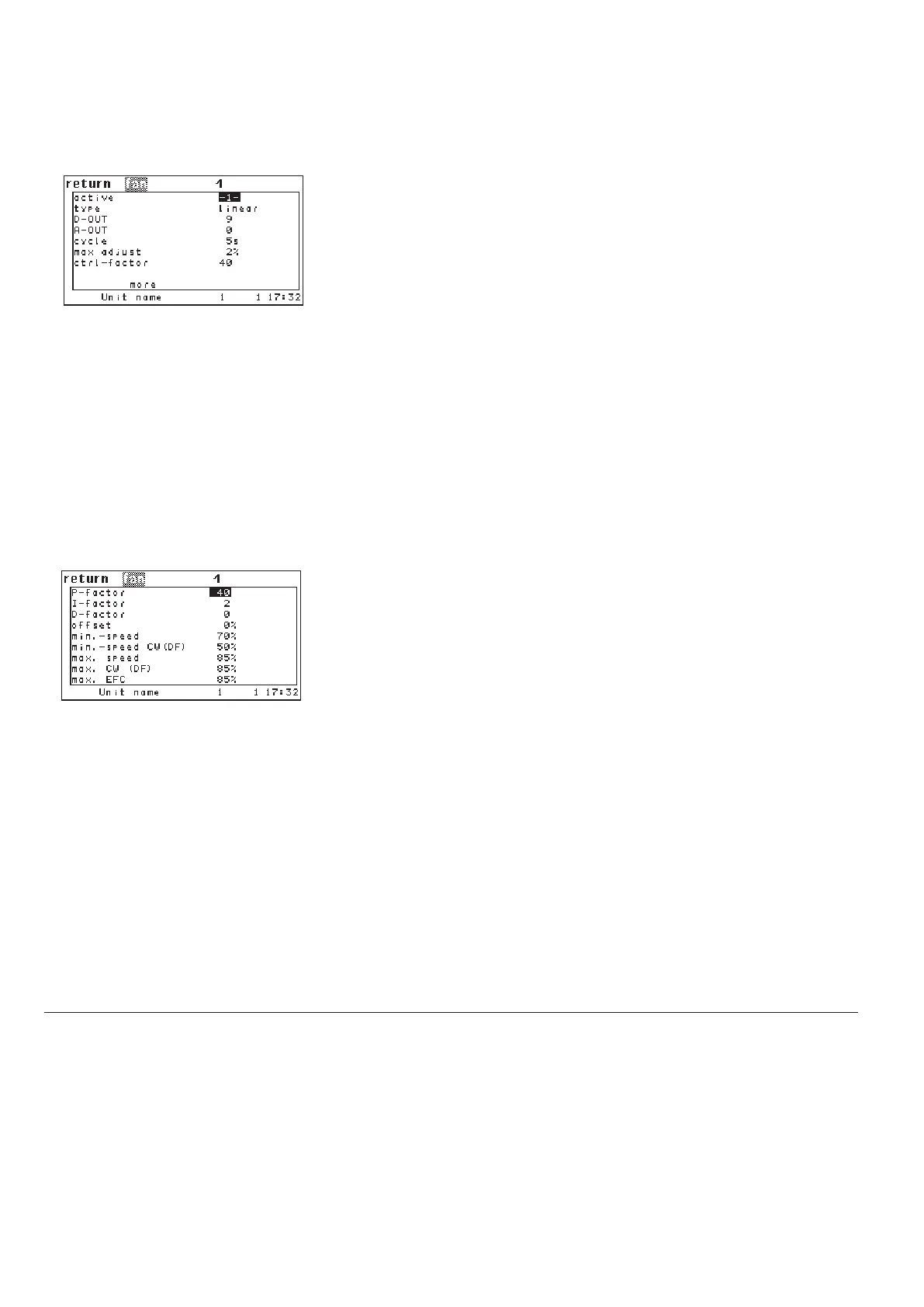
The corresponding commands:
Components/Air
Fan/...
By setting the parameter "ACTIVE" on 1 you add a fan to the configuration. With
"0" you disable the fan.
➊
In the next line you determine the fan type (2-point: fan with on/off control,
Linear: EC-fan with proportional speed control).
➋
With the parameter "DOUT" ➌ you determine a digital output for an on/off fan.
In case of a proportionally controlled fan the enabling signal is available at this
output.
With the parameter "AOUT" you adjust the analog output of the proportional
signal for a speed controlled fan.
➍
The parameters:
- control cycle
➎
- max. control correction ➏
- control factor ➐
are only necessary for the DFC control, which is explained in a separate manual
and for the differential pressure control. With these parameters the character-
istics of an integral control can be performed.
In the first lines of the following menu you can set the P-factor
➊, the I-factor ➋
and the D-factor
➌ for specifying the control characteristics. These three para-
meters are exclusively valid for differental temperature control (see chapter
6.7).
The offset is used to adapt the airflow to unexpected conditions on the site
(lower/higher pressure loss).
➍
The minimum speeds, which you can adjust in line 5 and 6, can only be bypas-
sed by the adjust ment in "REDUCE SPEED". The maximum speeds should be
adjusted according to the required layout airflow.
The minimum speed
➎ in line 5 and the maximum speed ➐ in line 7 are valid for
all units except for CW operation in dual fluid units.
The minimum speed CW(DF)
➏ in line 6 and the maximum speed ➑ in line 8 are
valid for CW operation in dual fluid units.
For dual fluid units the speed selection depends on the cooling priority. In case
of a malfunction changeover the corresponding speed is taken. For a detailed
description of the conditions for a malfunction changeover see page 53.
The parameter "max. EFC"
➒ is only necessary for the DFC control.
Type 1: On/off control
Type 2: Proportional control
fan 1 conf 1
fan 1 type 1
fan 1 dout 11
fan 1 aout 11
fan 1 concyc 8
fan 1 maxc 2
fan 1 fact 2
fan 1 pid kp 10
fan 1 pid ki 4
fan 1 pid kd 2
fan 1 offset -5
fan 1 min 60
fan 1 nmincw 40
fan 1 nmax 85
fan 1 nmaxcw 90
fan 1 nmaxefc 85
.../general
.../general/more
Config