2928
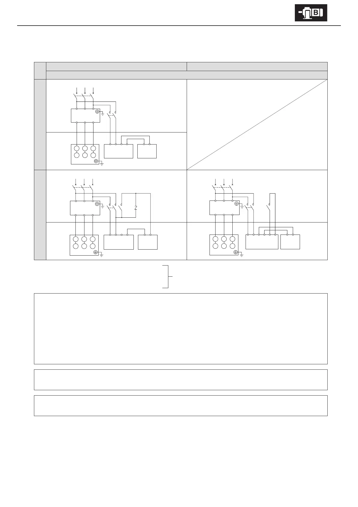
6. Wiring
■
With brake Inverter drive
Premium-eciency, 3-phase motor
Premium-eciency, 3-phase motor for inverter
FB-8E – FB-15E FB-20, FB-30
8 lead wires
Normal braking circuit
Control Panel Motor
Quick braking circuit
Control Panel
Control Panel
Motor
Motor
MC: Electromagnetic contactor
MCB: Breaker for wiring
VR: Varistor (for protecting contact points, rectier, etc.)
Customer to prepare.
- This diagram shows cases for motors with standard Japanese domestic specications. Please consult with us for motors with
overseas specications.
- For brake types, see Table 1-6 on P7.
- Brake action delay time is dierent for normal and quick braking circuits.
Table 7-2 on P35 shows action delay time. Choose the circuit that matches work requirements.
- Use a quick braking circuit to improve hoisting equipment and stopping precision.
- Use a quick braking circuit when a phase-advancing capacitor is mounted.
- For information on electromagnetic contactors and varistors for quick braking circuits, see Table 6-4 on P32.
- Use FB-20, FB-30 with quick braking circuits.
- FB-20, FB-30 are shipped with a short circuit plate connecting terminals 5 and 6. Remove the short circuit plate when wiring.
- Always use the inverter’s power source side for the brake power source.
- Match the opening and closing of the brake circuit’s electromagnetic contactor to the timing of the inverter control.
1234 MN
Rectier
Inverter
Brake
MCB
MC
RST
UVW
U1 V1 W1
V2 W2 U2
Motor
U1 V1 W1
V2 W2 U2
Motor
Inverter
RST
UVW
1234 MN
Rectier Brake
R ST
MCB
VR
MC
123456 MN
Rectier Brake
MC
R ST
MCB
Inverter
RST
UVW
U1 V1 W1
V2 W2 U2
Motor