3130
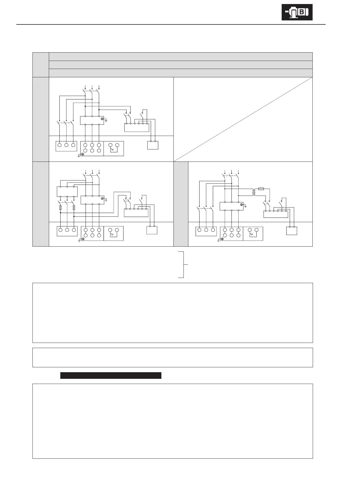
6. Wiring
■
With brake Inverter drive
AF motor for inverter
ESB-250, ESB-250-2
13 lead wires
AF motor for inverter with axial fan
Quick braking circuit
Indoor 200V class
Outdoor 200V class
Control Panel Motor
Quick braking circuit
Indoor 400V class
Control Panel
Quick braking circuit
Outdoor 400V class
Control Panel
Motor
Motor
MC: Electromagnetic contactor
MCB: Breaker for wiring
Tr: Transformer capacity 250–600VA, secondary voltage 200–220V
F: Fuse 3–5A
Customer to prepare.
- This diagram shows cases for motors with standard Japanese domestic specications. Please consult with us for motors with
overseas specications.
- For brake types, see Table 1-6 on P7.
- Use with a quick braking circuit. For information on electromagnetic contactors for quick braking circuits, see Table 6-4 on P32.
- Rectiers are external to the main unit. Rectiers are made for indoor use. Install in an area where they will not come into contact
with water, etc.
- The brake unit is for 200V class. For 400V class power sources, prepare a 400V/200V transformer.
- Always use the inverter’s power source side for the brake power source.
- Match the opening and closing of the brake circuit’s electromagnetic contactor to the timing of the inverter control.
In the case of
With axial fan (totally enclosed, ventilated types) , note the following items.
- Also connect a power source to the axial fan.
- For an indoor 400V class, the axial fan power source voltage will be 200V class.
- For special specications, specications may dier from the above. Check the manufacturing specications.
- Connect the fan so that it rotates in the same direction as that shown on the nameplate for direction of rotation.
(Normally, the air from the fan will blow in a direction from the anti-load side to the load side.)
- When the motor is shut down for a long period, also shut down the axial fan motor.
- Wire the mounted thermostat.
- Thermostat specication: Terminal symbols: T1, T2 and P1, P2 Operating function: Normal close (b contact point)
Operating temperature: 135
℃
(for thermal class 155 (F)) Maximum current: DC 24V, 18A; AC 230V, 13A
U1 V1 W1
V2 W2
T1 T2
U2
U V W
MCB1
MCB2
MotorThermostat
Axial fan
Inverter
RST
UVW
U V W
MCB2
FF
Axial fan
400V
Tr
200V
U1 V1 W1
V2 W2 U2
R ST
MCB1
Motor
Inverter
RS
UVW
T
T1 T2
Thermostat
123456
43
Rectier
Brake
MC
U1 V1 W1
V2 W2
T1 T2
U2
R
U V W
ST
MCB1
MCB2
MotorThermostat
Axial fan
Inverter
RST
UVW
123456
Rectier
MC
123456
43
Rectier
Brake
MC
Tr
F
400V 200V
Brake