3.0 Receiver Setup and Operation
- 17 -
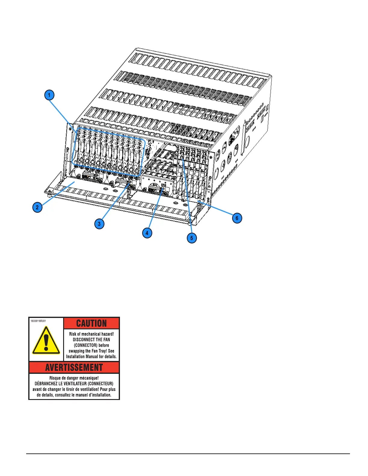
FIGURE 3-2: SG-System 5 front with door open
1. Line cards
2. Warning label
3. Primary display power connection
4. Secondary display power connection
5. PSTN line card
6. Line card extraction plate
FIGURE 3-3: SG-System 5 warning label
WARNING: To reduce the risk of electric shock, the product is provided with a grounding type power supply IEC receptacle. Connect product using
an appropriate IEC cable to a grounded receptacle.
Do not connect to a receptacle controlled by a switch.
l RS-232 Serial Automation Output: Provides serial connection to a local computer running automation software. A null modem serial cable must
be used.
l RS-232 Serial Printer Output: Provides serial connection to a local computer or serial printer. A null modem serial cable must be used.