4.0 Hardware Descriptions and Specifications
- 24 -
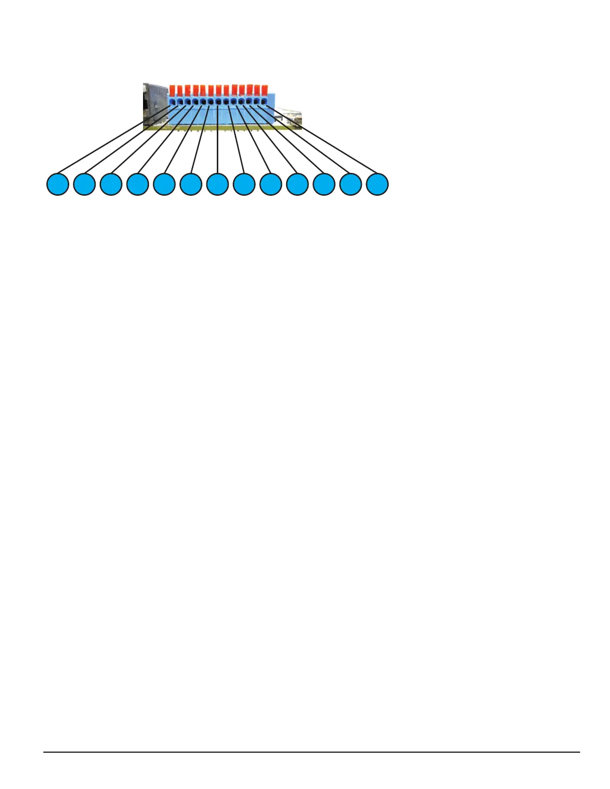
4.2.1 SG-CPM5 I/O terminal pin-outs
1 3 2 4 5 7 6 8 9 10 1211 13
1. Input1 UPS AC Failure: UPS AC normally closed output opens on failure.
2. GND Common (ground)
3. Input2 UPS DC Failure: UPS battery normally closed output opens on failure.
4. Input3 Remote ACK: When the SG-CPM5 is in manual mode, pressing the ack button (front panel) or connecting this input to
ground (typically using a button) acknowledges the first event on the LCD.
5. GND Common (ground)
6. Input Future use
7. OutputR1 Follow Buzzer: Relay contact closes following the buzzer caused by manual mode.
8. R1 Relay 1 Common
9. OutputR2 Trouble Output: Relay contact closes when the trouble (Status) LED activates.
10. R2 Relay 2 Common
11. OutputR3 Network Status: Relay contact closes when the network is present.
12. R3 Relay 3 Common
13. GND Common (Gound)
For ULC installations, the equipment shall be rack-mounted and powered by a permanently wired supply in accordance with C22.1, Canadian Electrical
Code, Part 1, Safety Standard for Electrical Installations, section 32. This equipment is intended to utilize the building emergency AC supply system for
their standby supply (e.g., UPS, batteries in conjunction with engine-driven generators).
4.2.1.1 UPS AC Failure – Pin 1
UPS AC Failure – this normally closed input is used with backup power supplies that support output activation for status indication. When this input is
activated, the SG-CPM5 indicates a trouble condition for UPS AC Fail (see SG-CPM5 option [609] for the primary and [610] for the secondary).
4.2.1.2 UPS DC Failure – Pin 3
UPS BATT Failure – this normally closed input is used with backup power supplies that support output activation for status indication. When this input
is activated the SG-CPM5 indicates a trouble condition for UPS Battery Fail (see SG-CPM5 option [611] for the primary and [612] for the secondary).
4.2.1.3 Remote ACK – Pin 4
Remote Ack – this input is used to provide a method to acknowledge an alarm condition (while the receiver is in manual mode) from a remote location.
The Remote Ack input is available any time that the front panel Ack button is available.
4.2.1.4 Buzzer Follow Output – Pin 7
Manual Mode Buzzer Follow – this output is activated in synchronization with the buzzer output of the SG-CPM5. When the buzzer is silenced/ended,
the output deactivates. This output is used to monitor the buzzer when the receiver is in a remote location.
4.2.1.5 Trouble Status Output – Pin 9
Trouble output – this output is activated with the trouble status output of the SG-System 5. Any enabled trouble condition on the system activates the
output. The output deactivates once all trouble conditions have been cleared. This output is used to monitor trouble conditions when the receiver is in a
remote location.