3.0 Receiver Setup and Operation
- 16 -
3.1 SG-System 5 quick install guide
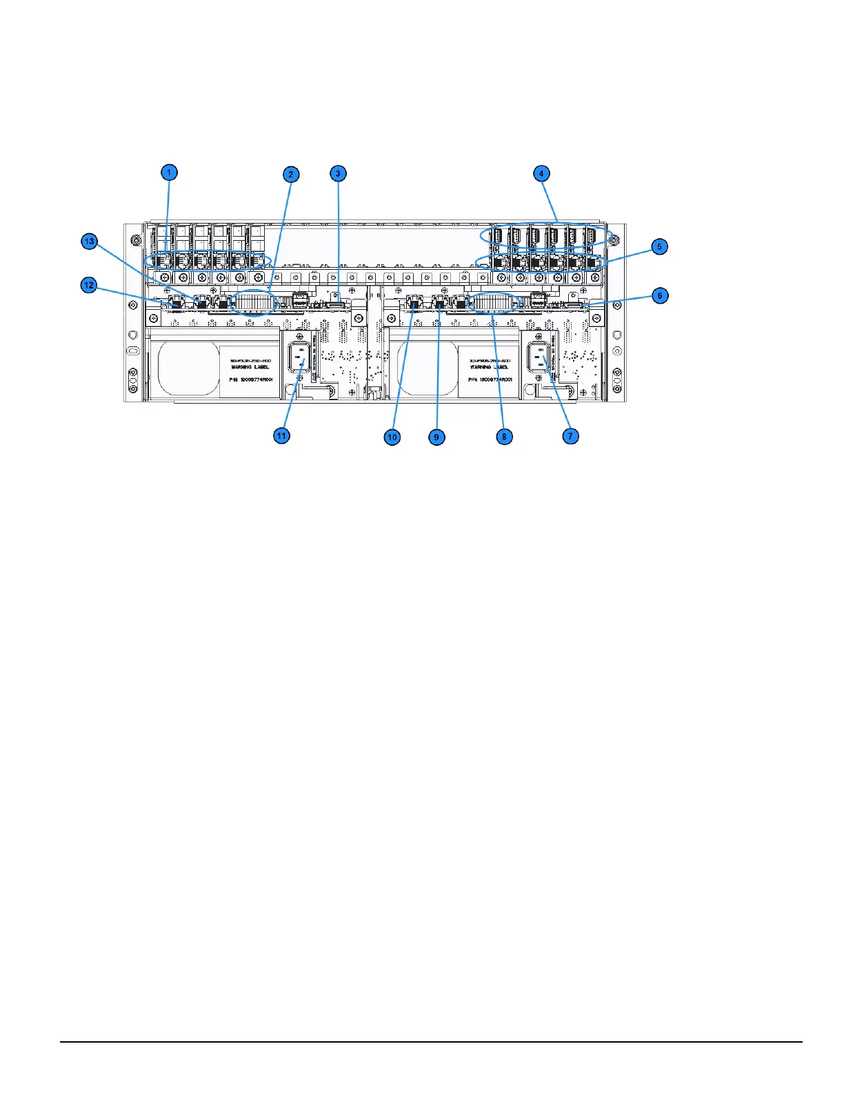
FIGURE 3-1: SG-System 5 connections (back)
1. Line card phone line connections
2. Secondary SG-CPM5 I/O terminal connections
3. Secondary SG-CPM5 display connection
4. Line card USB connections
5. Line card Ethernet connections
6. Primary SG-CPM5 display connection
7. Primary SG-PSU5 AC power connection
8. Primary SG-CPM5 I/O terminal connections
9. Primary SG-CPM5 automation and printer port
10. Primary SG-CPM5 Ethernet connection
11. Secondary SG-PSU5 AC power connection
12. Secondary SG-CPM5 Ethernet connection
13. Secondary SG-CPM5 automation and printer port
NOTE: This equipment must be operated by SERVICE PERSONS only within RESTRICTED ACCESS LOCATIONS; refer to this
Operating Manual for Safety Instructions.
NOTE: For equipment used at signal receiving centers and intended to facilitate IP communication (hubs, routers, NID, DSL/cable
modems), 24-hour backup power is required.
NOTE: To test the operation of LEDindicators and LCD:
From the LCD, click the menu at the top right>> login/options>>More Options>> Visual indicator test>>yes.
NOTE: When using private, corporate, and high-speed data networks, network access and domain access policies are set to restrict unau-
thorized network access and ‘spoofing’ or ‘denial of service’ attacks. Select an ISP that provides redundant servers/systems,
backup power, routers with firewalls enabled and methods to identify and protect against these types of attacks (‘e.g., ‘spoofing’,
'DoS').
NOTE: Install external devices connected to SG-CPM5 Ethernet, SG-CPM5 automation printer ports and SG-CPM5 I/O terminal con-
nections in the same room as the SG-System 5. Maintain 6.5 mm (1/4 inch) of separation between power limited and non-power lim-
ited circuits. Use power limited, supervised circuits only.