4.0 Hardware Descriptions and Specifications
- 25 -
4.2.1.6 Network Status Output – Pin 11
Network Status output – This output is activated when there is a network absent condition. Once the network connection is restored, this output deac-
tivates. This output is used to monitor the network status when the receiver is in a remote location.
4.2.2 SG-CPM5 Setup
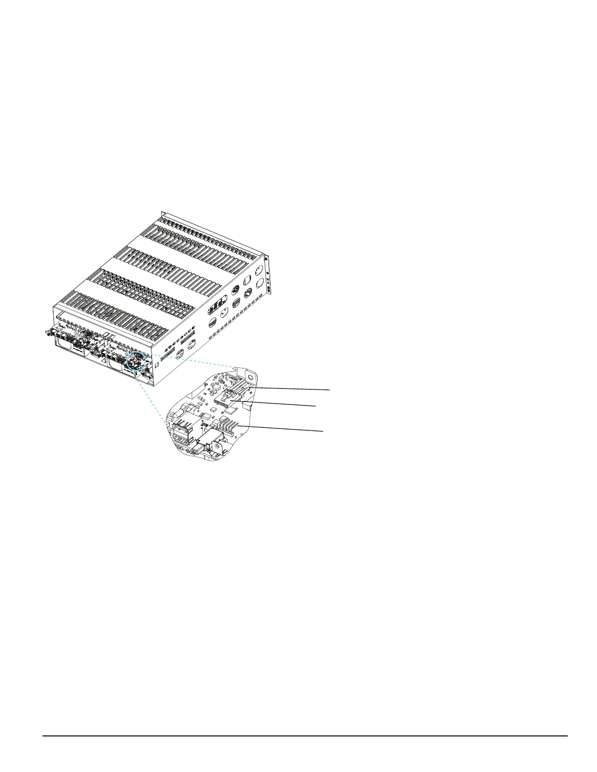
4.2.2.1 Connecting the SG-CPM5 Fan Cable
To connect the CPM's fan cable, partially slide the SG-CPM5 into the SG-MLRF5 and connect the cable to the SG-CPM5 board with the connector
facing up. Slide the SG-CPM5 all the way into the rack.
FIGURE 4-5: SG-CPM5 Fan Cable
Fan Cable
Fan Connector
Pin 1
4.2.2.2 Y-Cable
The Y-cable is used to connect the SG-CPM5’s RJ-45 port to serial cables. To connect it, plug it into the second RJ-45 port from the left.
4.2.2.3 RTC Battery
The SG-CPM5 has two replaceable A76 alkaline RTC batteries. Replace batteries approximately every five years.
To replace the RTC batteries, follow these steps:
1. Unfasten the SG-CPM5 thumb screws.
2. Partially remove the SG-CPM5 , disconnect the SG-CPM5 fan tray cable, then remove the SG-CPM5 fully.
3. Insert a small screwdriver into either side of the battery holder and push the battery out.
4. Insert the new battery into the holder (label up).
5. Repeat steps 3-4 for the other battery.
4.2.2.4 EMMC Memory
The SG-CPM5 has an optional add-on EMMC memory module that is required to expand the AHS table.
To replace the EMMC memory, follow these steps:
NOTE: If the EMMC is not already installed, please skip steps 3-4.
1. Unfasten the SG-CPM5 thumb screws.
2. Partially remove the SG-CPM5, disconnect the SG-CPM5 fan tray cable, then remove the SG-CPM5 fully.
3. Unfasten the two screws on the EMMC module.
4. Carefully lift the EMMC module off of the board.