SVAN 973 User Manual – Appendixes
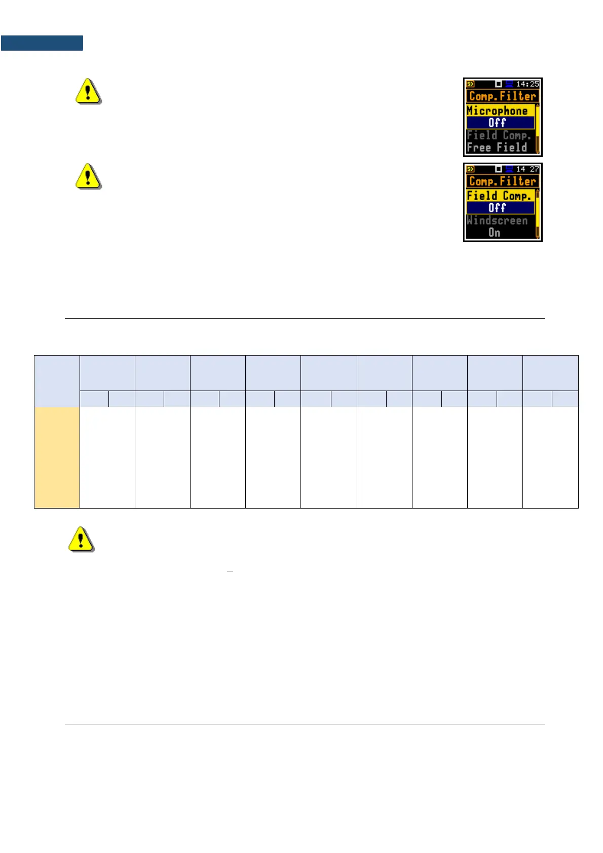
Note: For the conformance electrical tests, the microphone
compensation must be switched off (Microphone=Off)!
Note: For the frequency response evaluation in the acoustic
coupler the microphone compensation must be switched on
(Microphone=On) and the Free-filed compensations must be
switched off (Field Comp=Off).
The Windscreen compensation is switching off automatically.
Periodical test upper frequency 8 kHz
Linear Operating Ranges
Table C.1 Linear operating ranges for the sinusoidal signal and microphone sensitivity 11 mV/Pa
Note: For signals with the crest factor n > 1.41 upper measuring range of the RMS (LEQ
and SPL) is reduced. The valid upper limit can be calculated according to the below given
formula:
𝑨𝒏 = 𝟏𝟐𝟓 − 𝟐𝟎𝒍𝒐𝒈(𝒏/
√
𝟐 ), where A is the upper limit for the sinusoidal signal
Example: For the crest factor n = 10 the upper limit is A
10
= 108 dB
The starting point at which tests of level linearity shall begin 94.0 dB (74 dB for A filter @ 31.5 Hz).
Measuring frequency range of the acoustic pressure (-3 dB) 20 Hz ÷ 10 000 Hz.
Basic measurement error of the acoustic pressure < 0.7 dB (measured for the reference
conditions, see below).
Weighting filters (see part C.3)
Z according to IEC 61672-1:2013 for Class 2
A according to IEC 651 and IEC 61672-1:2013 for Class 2
B according to IEC 651 and IEC 61672-1:2013 for Class 2
C according to IEC 651 and IEC 61672-1:2013 for Class 2
 Loading...


