Chapter 1 Getting Started
The 5071A at a Glance
Operating and Programming Manual 7
Rear-Panel Connections
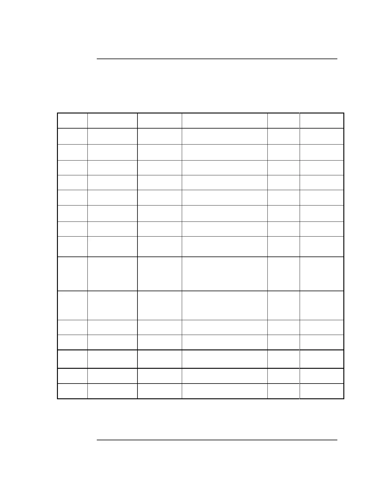
The item numbers in Table 1-1 correspond to the callouts in the adjacent
illustration on pages 5 and 6.
Table 1-1. Connector Descriptions
Output- Port 1,
5 or 10 MHz
Sinusoidal, 1 Vrms into 50Ω,
Nominal
Output- Port 1,
5 or 10 MHz
Sinusoidal, 1 Vrms into 50Ω,
Nominal
Sinusoidal, 1 Vrms into 50Ω,
Nominal
Sinusoidal, 1 Vrms into 50Ω,
Nominal
1pps, 20 µs wide, TTL
compatible, into 50Ω
100 ns to 100 µs wide, +2 to
+10V into 50ΩTTL) Threshold
Status Output,
Active Low
TTL Open Collector, 1.6 kΩ pull-
up to 5V
9Pin, Male,
D-sub
miniature
RS-232C, DTE Configuration
Internal
Standby
Battery
Disconnect
Switch Access
Switch disconnects Internal
Standby Battery.
22-42 Vdc, 100 Watts, Pinout:
+22 to +42 Vdc (pin A), Neg. dc
(pin C), Chassis Gnd (pinE),
pins B and D are not used
Fuses external dc power,
5 Amp fuse
120/240 Vac, 1.5/0.75 Amp
slow-blow fuse.
Fuses external dc power, 2.5 amp,
250 volt rating (P/N 2110-0952)
40-58 Vdc, 100W Max, as labeled
on rear panel
** Note: Items 9, 10 and 11 are not present on 48V option instruments.
 Loading...

