Appendix A Performance Tests
Rear-Panel Output Signal Checks
142 Operating and Programming Manual
Rear-Panel Output Signal Checks
Check the rear-panel outputs for appropriate signal waveform, frequency and
voltage.
Required Equipment
• BNC-to-BNC 1-meter cable (male connectors), model number HP/Agilent 10503A
• Type N (male)-to-BNC (female) adapter, part number 1250-0780
• 50 Feedthrough BNC (male) and (female) adapter, model number
HP/Agilent 10100C
• HP/Agilent 54600A General-Purpose 100 MHz Oscilloscope (or equivalent)
To check the rear-panel output connectors quickly for the presence of valid
output signals, perform the following:
The LCD display backplane light will turn off after approximately 4 minutes to
conserve energy if no front-panel key is pressed. Press any key to turn the
backplane light back on.
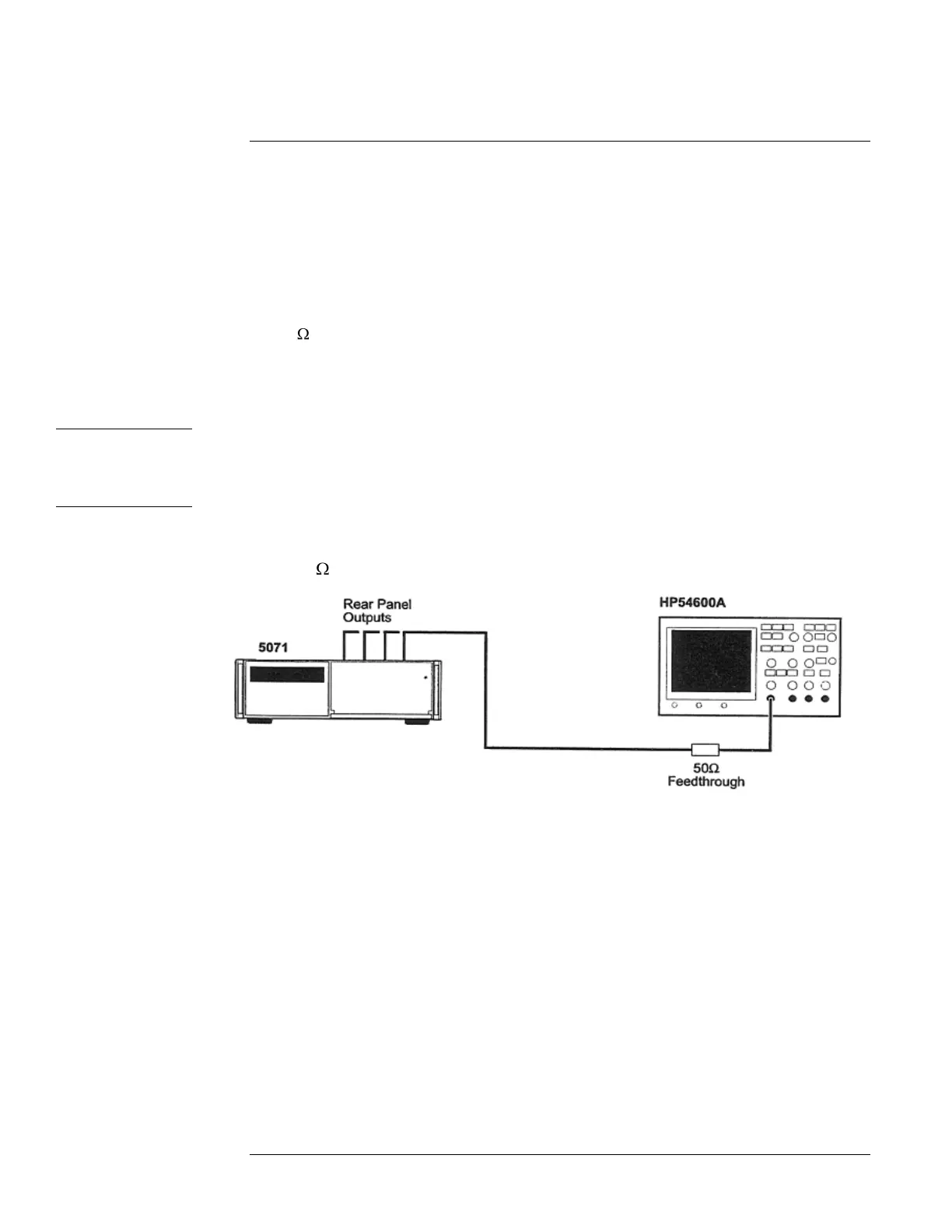
1 Connect one of the 5071A outputs to an input channel of the HP/Agilent 54600A
with a 50 feedthrough termination and BNC cable as shown in Figure A-1.
Figure A-1. Rear-Panel Outputs Verification Setup
2 On the HP/Agilent 54600A Oscilloscope, press Autoscale.
Use manual settings if needed to check the 1pps Outputs.
3 Verify that the output signal waveform, frequency, and nominal voltage correspond
to the values listed in Chapter 6, ―Specifications,‖ for the signal under test.
4 Repeat steps 1 through 4 for all outputs.
5 Mark Pass or Fail on the Performance Test Record, Line 2.
 Loading...

