BIOSTRENGTH LINE: Service & Maintenance manual - rev. 2.1
Page 3.10
Figure 3.2.3
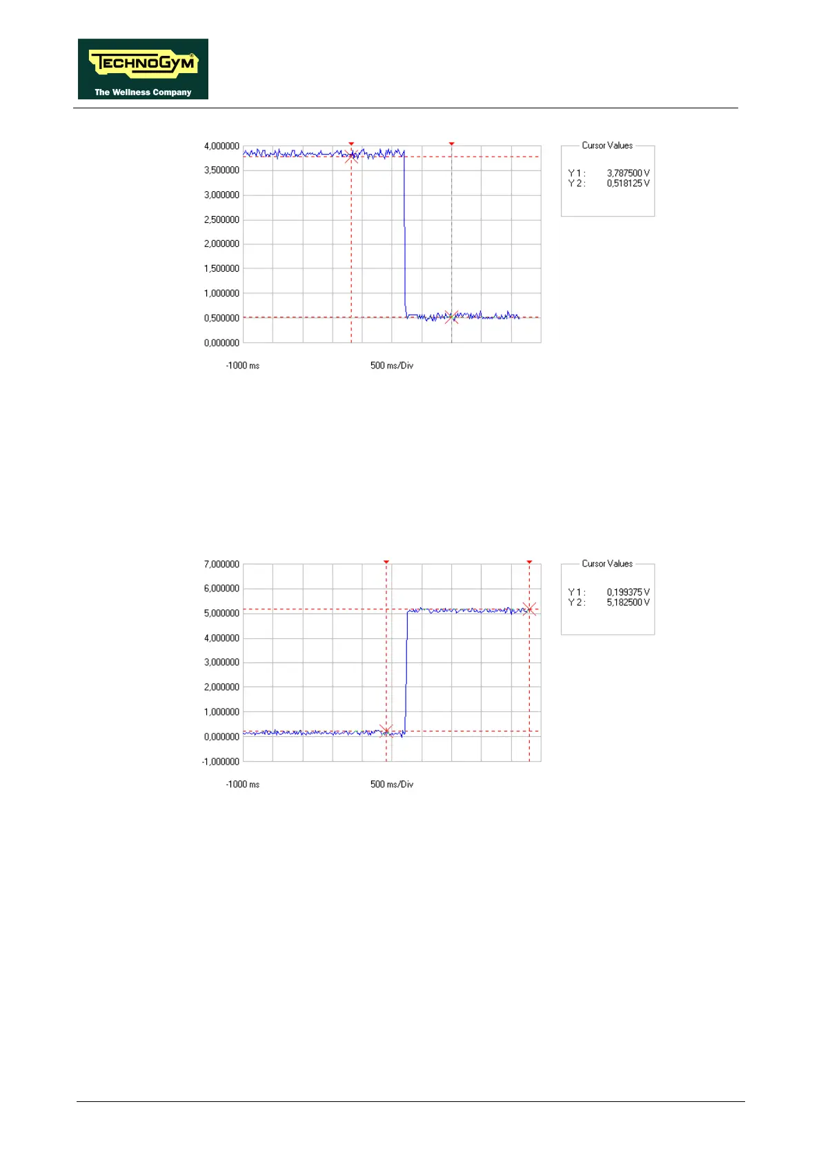
• Status signal
This is the signal generated by the Bio servo board (pins 15-1 on connector CN7) to notify the
CPU board (pins 15-1 on connector K4) of the solenoid status: if this signal is high (~ 5 V), no
current is circulating in the solenoid; if it is low (~ 0 V), current is circulating in the solenoid.
The figure below shows the switching of the status signal caused by selection of the additional
weight:
Figure 3.2.4
• Voltage on solenoid
This is the signal for the solenoid generated by the solenoid interface board (pins 5-6 on
connector CN3): when it is 24 Vdc the solenoid is powered; when it is 0 Vdc, the solenoid is not
powered.
The figure below shows the switching of the power supply signal caused by selection of the
additional weight:












 To Next Page