CROSS PERSONAL: Service & maintenance manual - rev. 1.1
Page 6.30
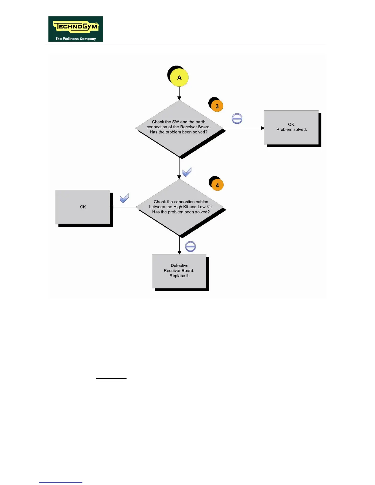
Follow the procedure step by step to correctly diagnose the problem. Take particular care with the
checks highlighted by circled numbers, which are described in detail below:
(1) Place the tester probes across pins 1 and 2 of the HD4 connector of the receiver on CU611
cable. The measured value should be +5Vdc.
(2) As at step (1) but on pin 1 and 5 on CN24 connector of the Display Board.
(3) Check the correct display SW version, according to the “EXCITE SW SMART TABLE” you
can find in TG Direct ,“NEWS” section.
Check the grounding of the Receiver Board, measuring the resistance value between:
a. The ground faston of receiver board and the ground node on the Power supply box of
the machine;
b. The ground node on the Power supply box of the machine and the main wall socket.
The measured value should be approximately lower than 1Ω (Ohm).
Check finally the grounding of the main wall socket, measuring that the following voltages
are present: