RUN 600 XTPRO: Service & Maintenance Manual - rev. 1.3
Page 2.6
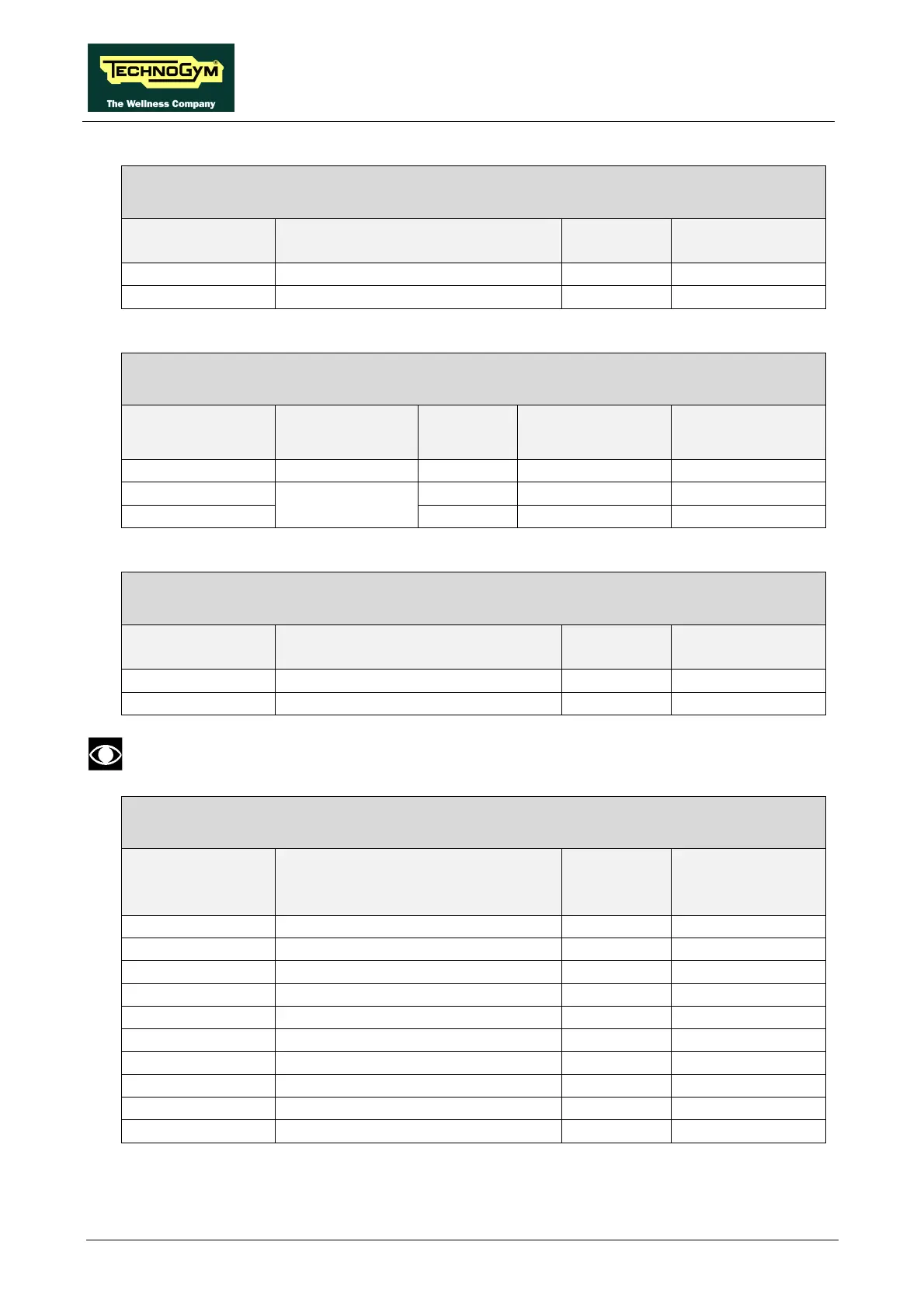
RX-13S: Emergency button cable
CPU board – Emergency button
CPU board
CN6
Signal Color Emergency
button
1 NC contact Black 2
2 Reference Clear 1
RX-13QA: Emergency button cable
Emergency button - CPU board – Patch cord
Emergency
button
Signal Color CPU board
CN5
Patch cord
CN11
1 Reference Brown - 1
2 Brown 2 -
-
Relay power
supply (-12 Vdc)
Blue 4 0
RX-1Q: Relay cable
Patch cord – Relay
Patch cord
CN11
Signal Color Relay
1 Relay power supply (12 Vdc) Blue 1
2 Reference Brown 0
The connection to pins “0” and “1” can be swapped.
XC-1: Output ports cable
CPU board – RJ45-RS232 board
CPU board
CN2
Signal Color RJ45-RS232
board
CN4
1 +12 Vdc flat 1
2 +12 Vdc flat 2
3 Tx to TGS flat 3
4 +5 Vdc flat 4
5 Rx from TGS flat 5
6 Tx to PC flat 6
7 Ground flat 7
8 Rx from PC flat 8
9 Ground flat 9
10 Ground flat 10