RUN XT: Service & Maintenance Manual - rev. 2.0
Page 2.2
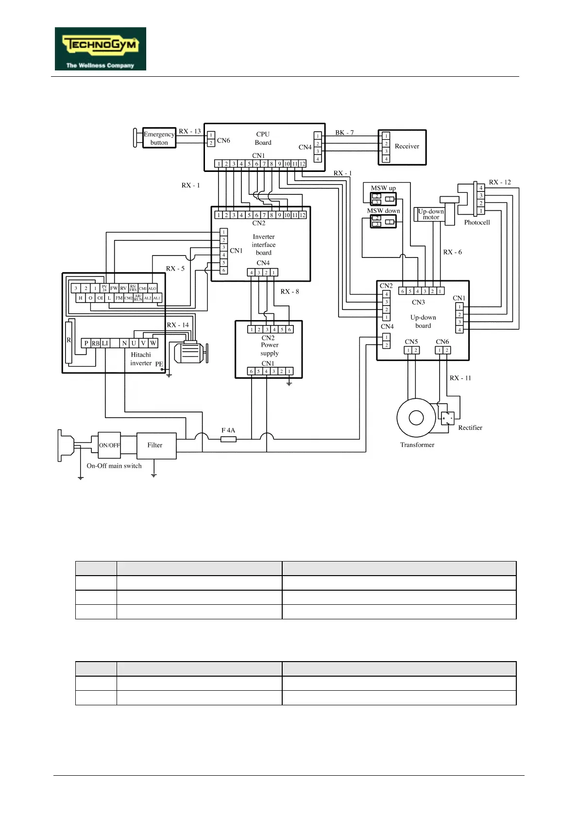
2.5. WIRING DIAGRAM FOR THE 220 MODEL
2.5.1. CONNECTORS
• CPU board
name type of connector connection
CN1 AMP MATE-N-LOCK 12-pin F. to up-down and inverter interface boards
CN2 AMP MODU II 2-pin M. to emergency button
CN4 AMP MODU II 4-pin M. to cardio receiver
• Power supply
name type of connector connection
CN1 PANDUIT 6-pin to mains electricity supply
CN2 PANDUIT 8-pin to inverter interface board