RUN XT: Service & Maintenance Manual - rev. 2.0
Page 7.30
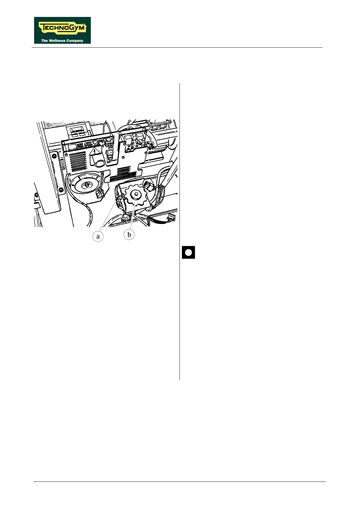
7.20. DISASSEMBLING THE PHOTOCELL
Figure 7.20-1
1. Carry out the procedures described in
paragraphs 7.7. “Disassembling the motor
guard” and 7.8. “Disassembling the front
plate”.
2. Disconnect connector a on the PHOTOCELL
board.
3. Using a 10-mm wrench, unscrew the 2 screws
fixing the cover of the protective housing of
encoder wheel b if present.
4. Open the cover.
5. Unscrew the 2 screws fixing the
PHOTOCELL board to the support using a
small Phillips screwdriver.
6. Remove the PHOTOCELL board.
There are 2 versions of photocell,
distinguished by the name of the printed
circuit board on which they are
mounted, which require a specific
version of the SW for the up-down
board microcontroller:
• board GF970711 operates with SW
RX42V2;
• board GF920415 operates with SW
RUNXT42.
To reassemble the PHOTOCELL, carry out the
above steps in reverse order.