RUN XT: Service & Maintenance Manual - rev. 2.0
Page 7.20
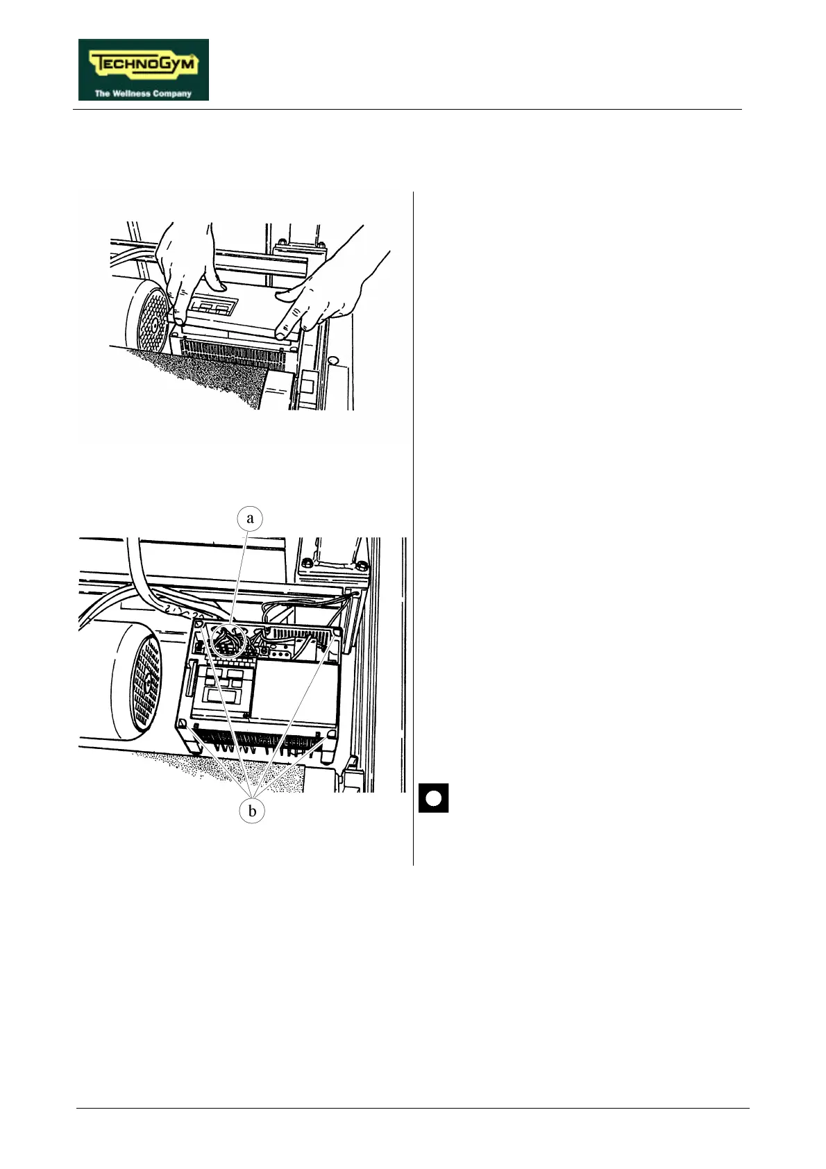
7.13. DISASSEMBLING THE INVERTER
Figure 7.13-1
1. Carry out the procedure described in
paragraph 7.7. “Disassembling the motor
guard”.
2. Remove the INVERTER cover, using a small
Phillips screwdriver to unscrew the fixing
screw, if present.
Figure 7.13-2
3. Disconnect the electrical cables a
small flat-head screwdriver for the logic
signals (upper terminal block) and a medium
flat-blade screwdriver for the power signals
(lower terminal block).
4. Disconnect the yellow-green ground
conductor of the inverter using a medium
Phillips screwdriver.
5. Unscrew the 4 fixing screws b using a 4-mm
Allen T wrench.
6. Remove the INVERTER.
To reassemble the INVERTER, carry out the
above steps in reverse order.
After completing this procedure,
calibrate the speed as instructed in
paragraph 8.7. .