RUN XT: Service & Maintenance Manual - rev. 2.0
Page 2.3
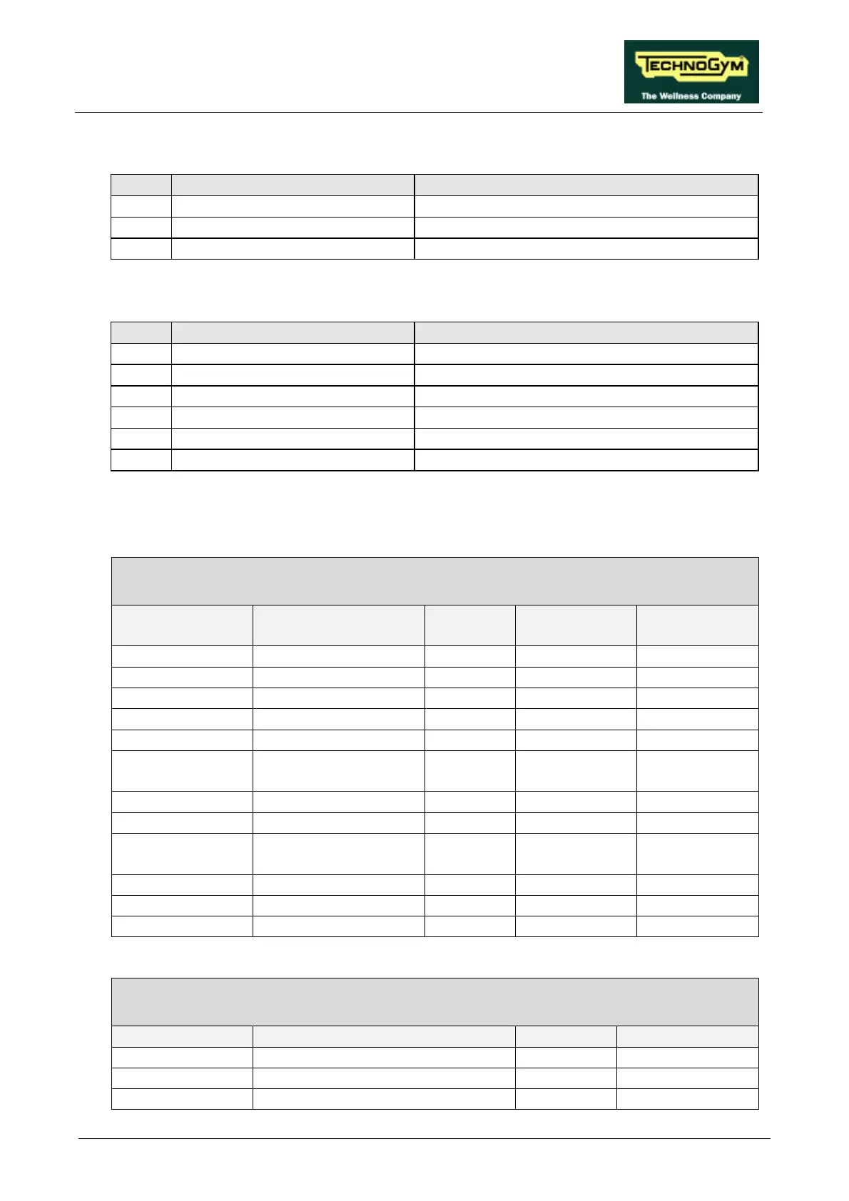
• Inverter interface board
name type of connector connection
CN1 AMP MATE-N-LOCK 6-pin F. to inverter
CN2 AMP MATE-N-LOCK 12-pin F. to CPU board
CN4 AMP MOD I 4-pin M to power supply
• Up-down board
name type of connector connection
CN1 AMP MOD II 4-pin M. to photocell
CN2 AMP MATE-N-LOCK 4-pin F. to CPU board
CN3 AMP MATE-N-LOCK 6-pin F. to up-down motor
CN4 AMP MATE-N-LOCK 2-pin F. to mains electricity supply
CN5 Sauro 2-pin to transformer
CN6 Sauro 2-pin to rectifier bridge
2.5.2. WIRING
RX-1: Internal connection cable
CPU – Inverter interface board – Up-down board
CPU/CN1 Signal Color Inverter interf.
board /CN2
Up-down
board/CN2
1 +12 V Blue 1 1 -
2 + 5 V Brown 1 2 -
3 ground Gray 1 3 -
4 -12 V White 5 -
5 not used Violet 12 -
6 Tread belt speed
reference (PWM)
Red 10 -
7 Start Black 8 -
8 Inverter alarm Orange 9 -
9
degree)
Brown 2 - 1
10 Up Pink - 2
11 Down Blue 2 - 3
12 ground Gray 2 - 4
BK-7: Heart rate monitor cable
CPU – Cardio receiver
CPU/CN4 Signal Color Receiver
1 +5 V Red 1
2 Pulse per beat Blue 2
3 ground Black 3