RUN XT: Service & Maintenance Manual - rev. 2.0
Page 6.21
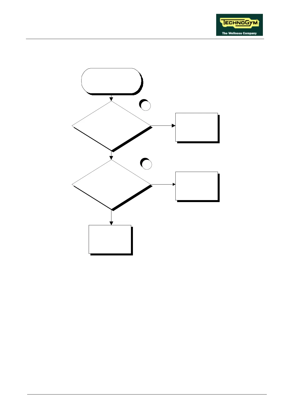
6.5. THE BELT MOTOR STARTS WITH DELAY
THE BELT
MOTOR STARTS
WITH DELAY
Are the Start and Speed PWM
signals correct at the output of the
CPU board?
Are the Start signal and the analog
speed reference signal correct at the
output of the inverter interface
board?
YES
NO
YES
Replace the inverter
interface board: see
paragraph 7.12.
1
2
NO
Replace the inverter: see
paragraph 7.13.
Replace the CPU board:
see paragraph 7.3.
Follow the procedure step by step to correctly diagnose the problem. Take particular care with the
checks highlighted by circled numbers, which are described in detail below:
(1) To check the Start signal, place a tester between pins 7 (signal) and 3 (ground) of connector
CN1 on the CPU board. When the belt is halted the measured voltage should be 0 Vdc,
whereas immediately after pressing the “Start” key on the display the measured voltage should
be 4.5 Vdc. To check the speed PWM signal, place a tester between pins 6 (signal) and 3
(ground) of connector CN1 on the CPU board. When the belt is halted the measured voltage
should be 5 Vdc, whereas immediately after pressing the “Start” key on the display the reading
should rapidly decrease until it reaches a fixed value corresponding to the selected speed. The
variation of the signal must be accompanied by a corresponding variation in the tread belt
speed: see Table 6.6-1 or Table 6.6-2.
(2) To check the Start signal, place a tester between pins 2 (signal) and 1 (ground) of connector
CN1 on the inverter interface board. When the belt is halted the reading should be -24.7 Vdc,
whereas immediately after pressing the “Start” key on the display the measured value should be
-2.7 Vdc. To check the speed PWM signal, place a tester between pins 5 (signal) and 6