RUN XT: Service & Maintenance Manual - rev. 2.0
Page 3.1
3. PRINCIPLES OF OPERATION
3.1. BLOCK DIAGRAM
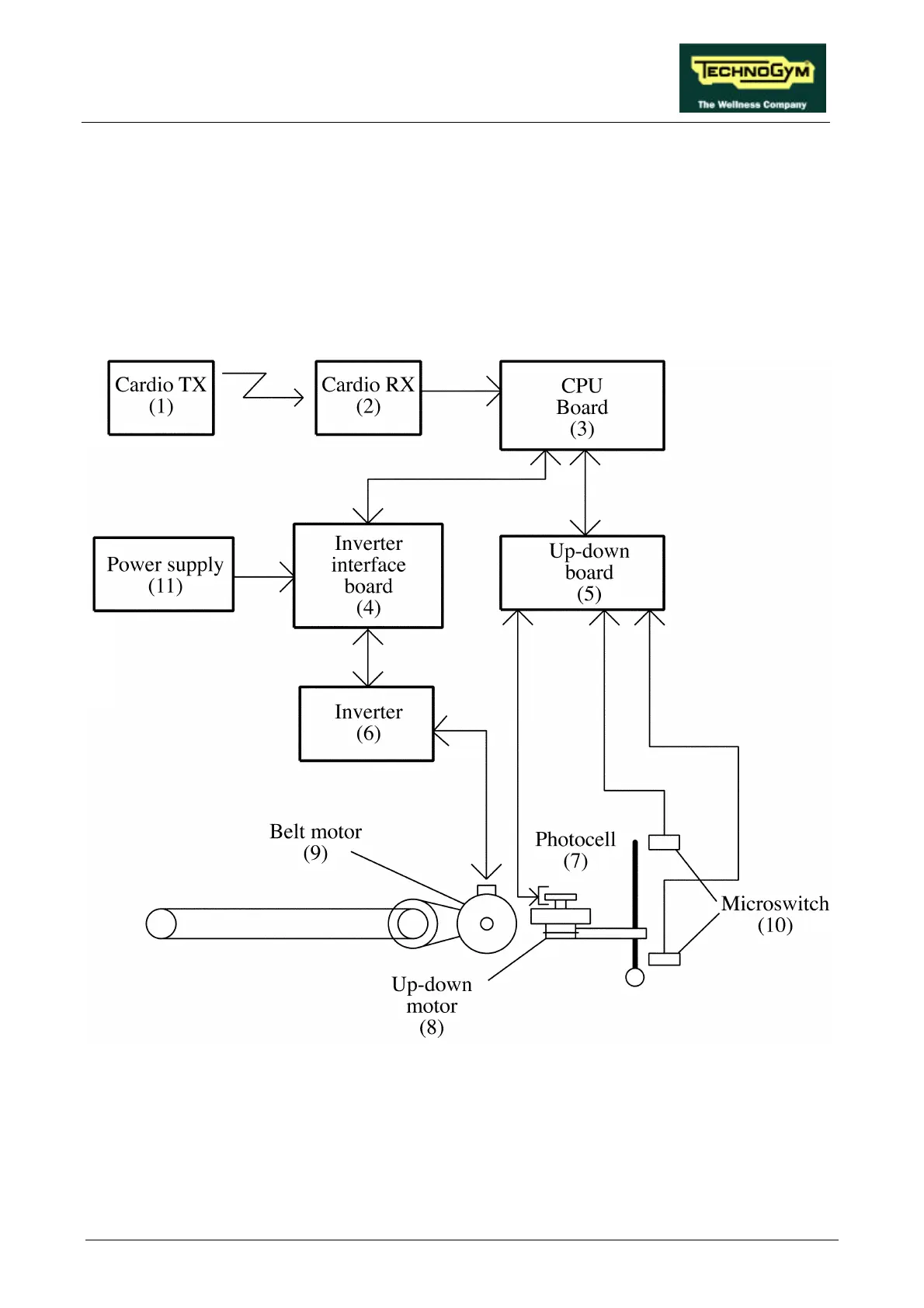
The machine block diagram is shown in the figure below:
(1) CARDIO TRANSMITTER
It is worn by the person using the machine, and transmits to the cardio receiver one pulse for
every heart beat that is detected.
(2) CARDIO RECEIVER
It is connected to the machine’s CPU board and receives the pulses sent by the transmitter. Its
reception area is approximately a circle of 1 meter of radius. If there is electromagnetic noise