RUN XT: Service & Maintenance Manual - rev. 2.0
Page 7.27
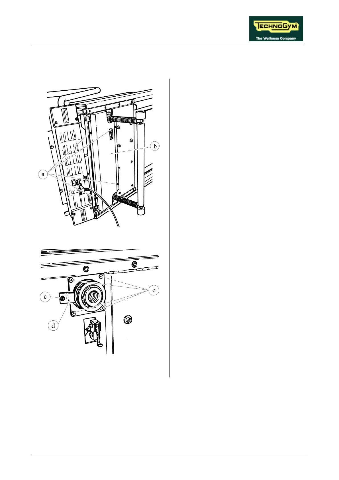
7.18. DISASSEMBLING THE LEAD SCREW NUTS
Figure 7.18-1
1. Place the machine in its maximum elevation
position.
2. Carry out the procedures described in
paragraphs 7.7. “Disassembling the motor
guard” and 7.8. “Disassembling the front
plate”.
3. Overturn the machine on its right hand side.
4. Using a large Phillips screwdriver unscrew
the 4 self-tapping screws a.
5. Remove the belt guard b.
6. Carry out the procedure described in
paragraph 7.17. “Disassembling the elevation
bars”.
Figure 7.18-2
7. Back off the bearing clamp screw c using a 4-
mm Allen T wrench.
8. Rotate the clamp d.
9. Unscrew the 4 screws e using a 4-mm Allen
T wrench.
Continued on the following page →