RUN XT: Service & Maintenance Manual - rev. 2.0
Page 6.32
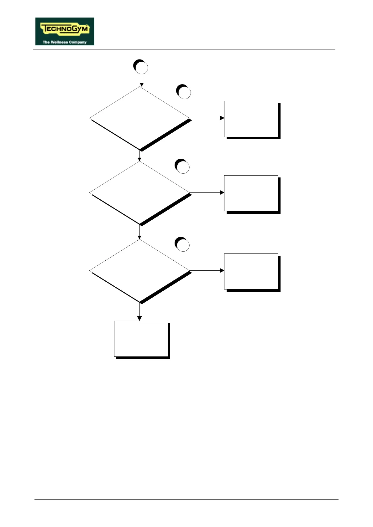
A
Is the limit switch associated with the
non-illuminated LED tripped?
YES
Check the position and/or
replace the limit switch:
see paragraph 7.19.
NO
Is the power supply to the limit
switch associated with the
non-illuminated LED correct?
YES
Replace the limit switch:
see paragraph 7.19.
NO
Does the up-down board send the
correct power supply to the limit
switch associated with the
non-illuminated LED?
NO
Check and/or replace
cable RX-6 connecting
the up-down board to the
limit switches
YES
Replace the up-down
board: see paragraph
7.12.
6
5
4
Follow the procedure step by step to correctly diagnose the problem. Take particular care with the
checks highlighted by circled numbers, which are described in detail below:
(1) The machine is considered to have reached a travel limit when the corresponding limit switch is
tripped. The lower limit switch is tripped when its lever is pressed, while the upper limit switch
is tripped when its lever is released.
(2) If the machine fails to move downward, place the tester probes between pins 4 (ground) and 3
(signal) of connector CN2 on the up-down board: the measured voltage should be
approximately 5 Vdc. If the machine fails to move upward, place the tester probes between
pins 4 (ground) and 2 (signal) of connector CN2 on the up-down board: the measured voltage
should be approximately 5 Vdc.