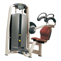
7. Push outward on frame tubes d, as indicated
by the arrows, in order to insert the
projections e of the upper machine frame
between them.
8. Inside tubes d there are two screws on either
side that must be inserted into the
corresponding holes on projections e. Make
sure none of the nuts and washers, later
needed to secure the upper frame, are yet
inserted.
9. At the same time, fit end piece f onto the
main machine frame as indicated by the
arrow.
10. Fix the upper frame to g using the two screws
provided.
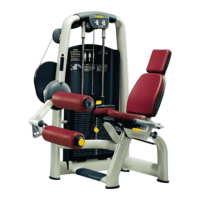
11. Lock down the 4 nuts h of the existing
screws on the main machine frame, also
inserting one washer on each screw.
12. Replace the cap.
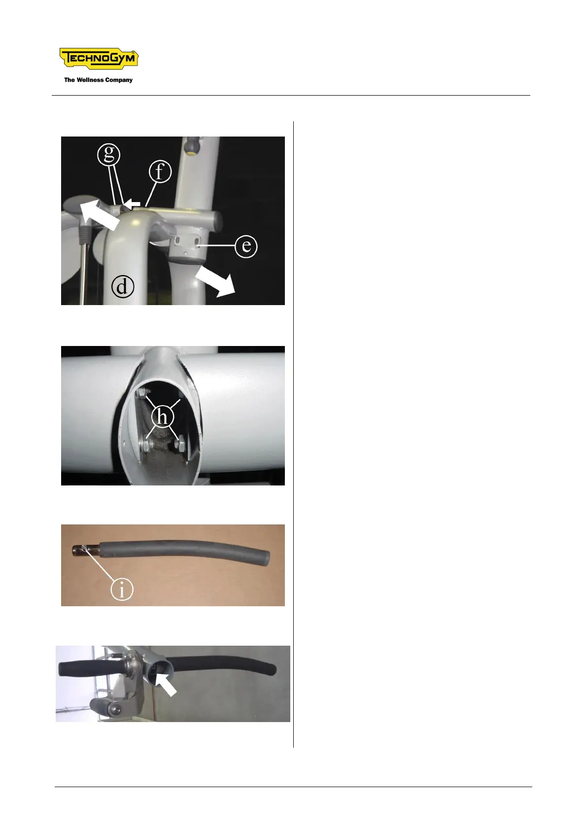
14. Fit the handles on the upper frame, so that
they bend downward, and secure by locking
down the screw inside the tube, indicated in
the figure.
15. Replace the cap.