--
c.
Move the cable from the
CH
1 OR X input connector
to
the
CH
2
OR
Y input connector. Set the VERTICAL
MODE switch to
CH
2.
d. Repeat part b using the Channel 2 controls.
2. Check Store Deflection Accuracy
a.
Set:
CH
2 VOL TS/DIV
STORE/NON STORE
POSITION CURS/
2 mV
STORE {button
in)
SELECT WAVEFORM POSITION CURS
(button
in)
b.
Use the CURSORS control and SELECT C1/C2
switch
to
set one cursor at the bottom and the other cur-
sor at the top of the square wave.
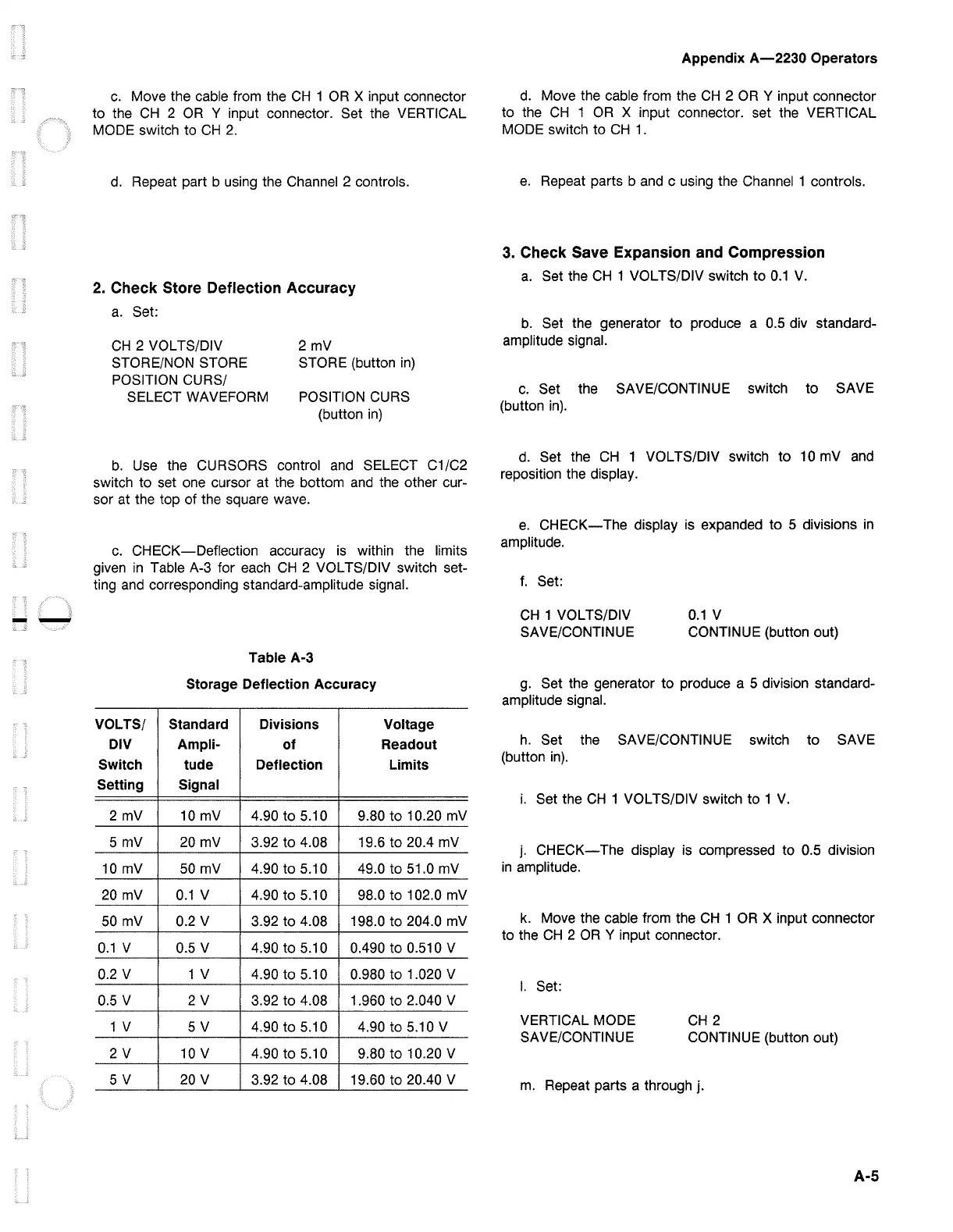
c.
CHECK-Deflection
accuracy is within the limits
given
in
Table A-3 for each
CH
2 VOL TS/DIV switch set-
ting and corresponding standard-amplitude signal.
Table A-3
Storage Deflection Accuracy
VOLTS/ Standard Divisions Voltage
DIV Ampli-
of
Readout
Switch
tude
Deflection
Limits
Setting Signal
2 mV 10 mV 4.90 to 5.10 9.80
to
10.20 mV
5 mV 20 mV 3.92 to 4.08 19.6
to
20.4 mV
10 mV 50 mV 4.90 to 5.10 49.0
to
51.0 mV
20 mV
0.1
V 4.90 to 5.10 98.0
to
102.0 mV
50 mV 0.2 V 3.92
to
4.08 198.0
to
204.0 mV
0.1
V 0.5 V 4.90
to
5.10 0.490
to
0.510 V
0.2 V 1 V 4.90 to 5.10 0.980
to
1.020 V
0.5 V
2V
3.92 to 4.08
1.960
to
2.040 V
1 V
5V
4.90
to
5.10 4.90 to 5.10 V
2V
10 V 4.90
to
5.10 9.80
to
10.20 V
5V
20 V
3.92
to
4.08
19.60 to 20.40 V
Appendix
A-2230
Operators
d.
Move the cable from the
CH
2
OR
Y input connector
to
the
CH
1
OR
X input connector. set the VERTICAL
MODE switch
to
CH
1.
e.
Repeat parts b and c using the Channel 1 controls.
3. Check Save Expansion and Compression
a.
Set the
CH
1 VOLTS/DIV switch
to
0.1
V.
b.
Set the generator
to
produce a 0.5 div standard-
amplitude signal.
c.
Set the SAVE/CONTINUE switch
to
SAVE
(button
in).
d. Set the
CH
1 VOL TS/DIV switch
to
10 mV and
reposition the display.
e.
CHECK-The
display is expanded
to
5 divisions
in
amplitude.
f.
Set:
CH
1 VOL TS/DIV
SAVE/CONTINUE
0.1
V
CONTINUE (button out)
g. Set the generator
to
produce a 5 division standard-
amplitude signal.
h.
Set the SAVE/CONTINUE switch
to
SAVE
(button
in).
i.
Set the
CH
1 VOLTS/DIV switch
to
1
V.
j.
CHECK-The
display is compressed to 0.5 division
in
amplitude.
k. Move the cable from the
CH
1
OR
X input connector
to
the
CH
2
OR
Y input connector.
I.
Set:
VERTICAL MODE
SAVE/CONTINUE
CH
2
CONTINUE (button out)
m.
Repeat parts a through j.
A-5

 Loading...


