---
Basic Applications-2230 Operators
C
f
I
.t.
100
I
so
ov ov
l+rr•
·-~
~-
·-•-t·~
,-~•·
•
i
NEGATIVE OFFSET
"
I;
I
I
t
r··
I
I
st;,mv
S~us
I
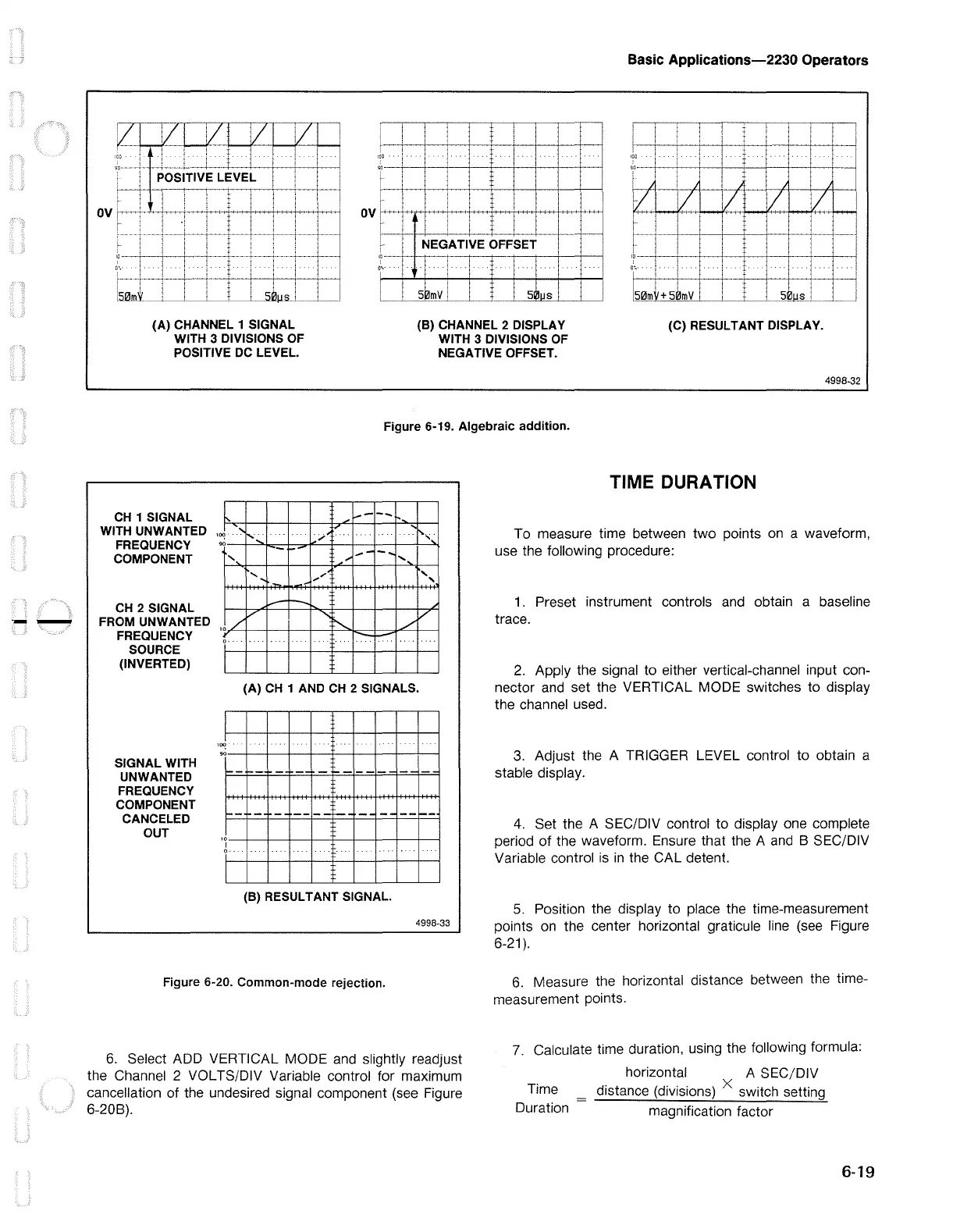
(A) CHANNEL 1 SIGNAL
WITH 3 DIVISIONS OF
POSITIVE DC LEVEL.
(B) CHANNEL 2 DISPLAY
WITH 3 DIVISIONS OF
NEGATIVE OFFSET.
(C) RESULTANT DISPLAY.
4998-32
Figure 6-19. Algebraic addition.
CH
1 SIGNAL
WITH UNWANTED
FREQUENCY
COMPONENT
CH 2 SIGNAL
FROM UNWANTED
FREQUENCY
SOURCE
(INVERTED)
SIGNAL WITH
UNWANTED
FREQUENCY
COMPONENT
CANCELED
OUT
,_
I
I°'!.
_i..----
•,
.,,..-
-
...
_.,,
.........
(A)
CH 1 AND
CH
2 SIGNALS.
.
··I···
'
'
,
,oo--1------1---1--1-----'!'---1---1--l----.l..-""'"
~-
...
-
,.__
·-
--
--L--
,0
-+----+-----+------+-+----+-----+---+-+----<
I
~
..
(B) RESULT ANT
SIGNAL
4998-33
Figure 6-20. Common-mode rejection.
6.
Select ADD VERTICAL MODE and slightly readjust
the Channel 2 VOL TS/DIV Variable control for maximum
cancellation of the undesired signal component (see Figure
6-20B).
TIME DURATION
To measure time between
two
points
on
a waveform,
use the following procedure:
1 . Preset instrument controls and obtain a baseline
trace.
2.
Apply the signal to either vertical-channel input con-
nector and set the VERTICAL MODE switches to display
the channel used.
3.
Adjust the A TRIGGER LEVEL control to obtain a
stable display.
4.
Set the A SEC/DIV control to display one complete
period
of
the waveform. Ensure that the A
and
B SEC/DIV
Variable control
is
in
the CAL detent.
5.
Position the display to place the time-measurement
points on the center horizontal graticule line (see Figure
6-21
).
6.
Measure the horizontal distance between the time-
measurement points.
7.
Calculate time duration, using the following formula:
horizontal A SEC/DIV
distance (divisions) X switch setting
Time
Duration
magnification factor
6-19

 Loading...


