Operator's Checks and
Adjustments-2230
Operators
TRACE ROTATION ADJUSTMENT
NOTE
Normally, the trace will be parallel to the center hor-
izontal graticule
line,
and TRACE ROTATION adjust-
ment is
not
required.
1.
Preset the instrument controls
and
obtain a baseline
trace as described
in
"Initial Setup."
2.
Use the Channel 1 POSITION control to move the
baseline trace to the center horizontal graticule line.
3. If the baseline trace
is
not parallel to the center hor-
izontal graticule line, use a small-bladed screwdriver or
alignment tool to adjust the TRACE ROTATION control to
align the trace with the graticule line.
PROBE COMPENSATION
Misadjustment of probe compensation
is
a source of
measurement error. The attenuator probes are equipped
with a compensation adjustment. To ensure optimum
measurement accuracy, always check probe compensation
before making measurements. Probe compensation
is
accomplished by:
1 . Preset the instrument controls
and
obtain a baseline
trace
as
described
in
"Initial Setup."
2.
Connect the two 1
OX
probes (supplied with the
instrument) to the
CH
1
OR
X
and
CH
2
OR
Y input con-
nectors. Observe that the
CH
1 VOL TS/DIV readout
changes from 5
mV
to
50
mV
when the 1
OX
probe
is
attached to the
CH
1
OR
X input.
3.
Remove the hook tip from the
end
of each probe.
NOTE
While
the probe tip is
in
the PRB ADJ connector,
use care not to to break
off
the probe tip.
4.
Insert the Channel 1 probe tip into the
PRB
ADJ
connector.
5.
Use
the
CH
1 POSITION control to vertically center
the display. If necessary, adjust the A TRIGGER LEVEL
control to obtain a stable display
on
the plus (OUT)
SLOPE.
5-2
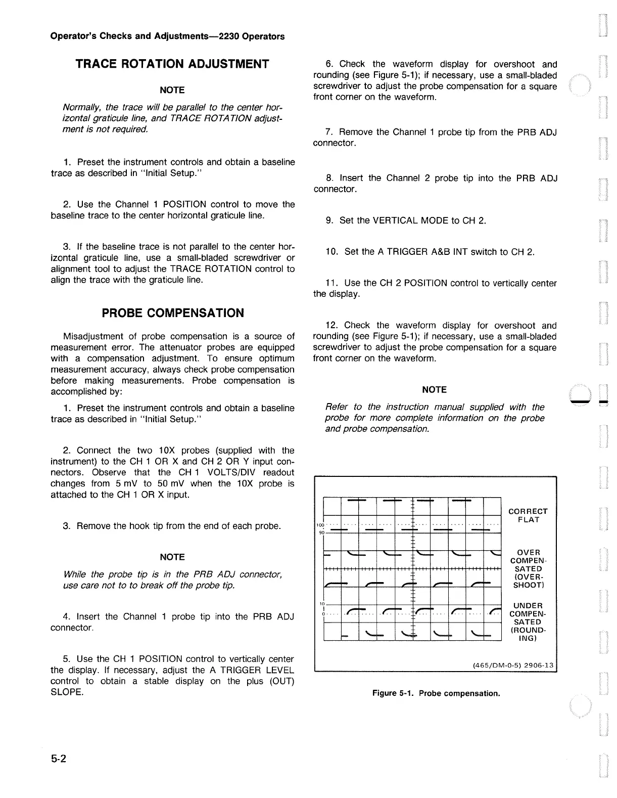
6.
Check the waveform display for overshoot and
rounding (see Figure
5-1
);
if necessary, use a small-bladed
screwdriver to adjust the probe compensation for a square
front corner
on
the waveform.
7.
Remove the Channel 1 probe tip from the PRB ADJ
connector.
8.
Insert the Channel 2 probe tip into the PRB ADJ
connector.
9.
Set the VERTICAL MODE to
CH
2.
10. Set the A TRIGGER A&B INT switch to
CH
2.
11. Use the
CH
2 POSITION control to vertically center
the display.
12. Check the waveform display for overshoot
and
rounding (see Figure
5-1
);
if necessary, use a small-bladed
screwdriver to adjust the probe compensation for a square
front corner
on
the waveform.
NOTE
Refer to the instruction manual supplied with the
probe for more complete information on the probe
and probe compensation.
CORRECT
FLAT
OVER
COMPEN-
SATED
(OVER-
SHOOT)
UNDER
COMPEN-
SATED
(ROUND-
ING)
(465/DM-0-5)
2906-13
Figure 5-1. Probe compensation.
.,_,.,....,

 Loading...


