--
PHASE DIFFERENCE
In
a similar manner to "Time Difference", phase com-
parison between two signals of the same frequency
can
be
made using the dual-trace feature of the instrument. This
method of phase difference measurement can
be
used up
to the frequency limit of the vertical system. To make a
phase comparison, use the following procedure:
1 . Preset instrument controls and obtain a baseline
trace, then set the A TRIGGER A&B INT switch to
CH
1.
2.
Set both AC-GND-DC switches to the same
position, depending on the type of input coupling desired.
3.
Using either probes or coaxial cables with equal
time delays, connect a known reference signal to the
Channel 1 input and the unknown signal to the Channel 2
input.
4.
Select BOTH VERTICAL MODE; then select either
ALT or CHOP, depending
on
the frequency
of
the input
signals. The reference signal should precede the com-
parison signal
in
time.
5.
If the two signals are of opposite polarity, press
in
the Channel 2 INVERT button to invert the Channel 2
display.
6.
Set both VOL TS/DIV switches and both Variable
controls so the displays are equal
in
amplitude.
7.
Adjust the A TRIGGER LEVEL control for a stable
display.
8.
Set the A SEC/DIV switch to a sweep speed which
displays about one full cycle of the waveforms.
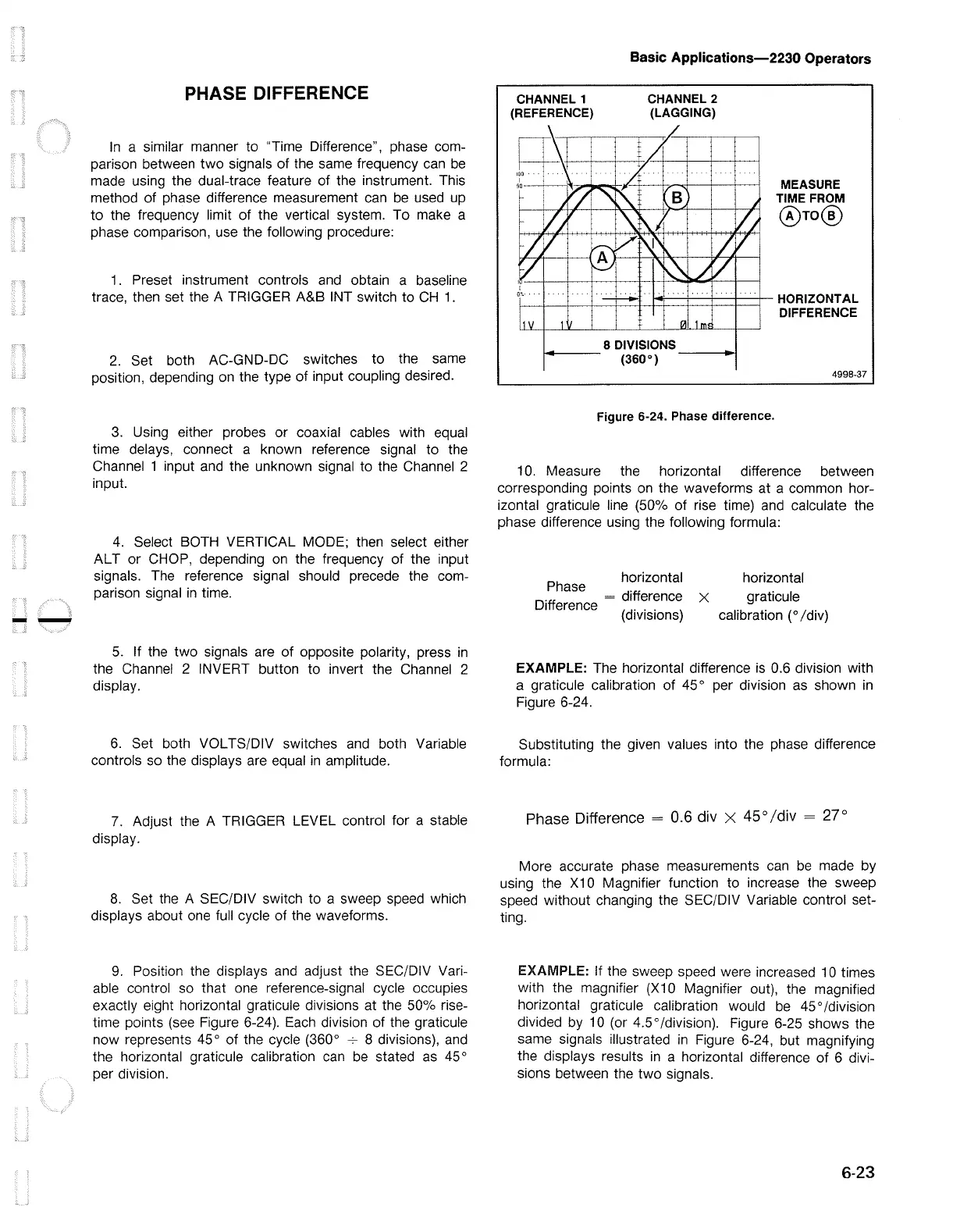
9.
Position the displays and adjust the SEC/DIV Vari-
able control so that one reference-signal cycle occupies
exactly eight horizontal graticule divisions at the 50% rise-
time points (see Figure 6-24).
Each
division of the graticule
now represents 45° of the cycle (360°
---;-
8 divisions), and
the horizontal graticule calibration
can
be
stated
as
45°
per division.
Basic Applications-2230 Operators
CHANNEL 1
(REFERENCE)
ffi--+--+-1
i i I
~i
8 DIVISIONS
MEASURE
TIME FROM
@ro@
i----
(360°)
__
__,
4998-37
Figure 6-24. Phase difference.
10. Measure the horizontal difference between
corresponding points
on
the waveforms at a common hor-
izontal graticule line (50%
of
rise time) and calculate the
phase difference using the following formula:
Ph
horizontal
ase d'ff
. = , erence x
Difference (d' . . )
1v1s1ons
horizontal
graticule
calibration (
0
/div)
EXAMPLE:
The horizontal difference
is
0.6 division with
a graticule calibration of 45 ° per division
as
shown
in
Figure 6-24.
Substituting the given values into the phase difference
formula:
Phase Difference = 0.6 div X 45° /div = 27°
More accurate phase measurements
can
be
made by
using the
X1
0 Magnifier function to increase the sweep
speed without changing the SEC/DIV Variable control set-
ting.
EXAMPLE:
If the sweep speed were increased 1 O times
with the magnifier (X10 Magnifier out), the magnified
horizontal graticule calibration would
be
45
° /division
divided by
10
(or 4.5 ° /division). Figure 6-25 shows the
same signals illustrated
in
Figure 6-24, but magnifying
the displays results
in
a horizontal difference of 6 divi-
sions between the two signals.
6-23

 Loading...


