--
5.
If necessary, use the MENU to set the time mea-
surement mode to DELTA TIME (at power-up, the default
is DELTA TIME).
6.
Set the POSITION CURS/SELECT WAVEFORM
switch to the POSITION CURS position (button
in).
7.
Use the CURSORS control to move the active cur-
sor to the start
of
the time to
be
measured.
8.
Push the SELECT
C1
/C2 button to select the other
cursor, and use the CURSORS control to move the cursor
to the end of the time to
be
measured.
9.
Read the time duration (between the cursors) from
the crt readout.
Frequency
1 . Preset instrument controls and obtain a baseline
trace.
2.
Set the STORE/NON STORE switch to the STORE
position (button
in).
3.
Select a VOL TS/DIV switch setting that gives the
desired vertical deflection.
4.
Set the A SEC/DIV switch to display one complete
period of the waveform to
be
measured.
5.
Use the MENU to set the time measurement mode
to 1/DELTA TIME.
6.
Set the POSITION CURS/SELECT WAVEFORM
switch to the POSITION CURS position (button
in).
7.
Use the CURSORS control to move the active cur-
sor to the start of the frequency to
be
measured.
8.
Push the SELECT C1/C2 button to select the other
cursor, and use the CURSORS control to move the cursor
to the end of the frequency to
be
measured.
9.
Read the frequency (between the cursors) from the
crt
readout.
Basic Applications-2230 Operators
Rise Time
Rise-time measurements use the same methods
as
time duration, except that the measurements are made
between the 10% and 90% points
on
the leading edge
of
the waveform.
Fall
time
is
measured between the 90% and
10%
points
on
the waveform trailing edge.
1 . Preset instrument controls and obtain a baseline
trace.
2.
Set the STORE/NON STORE switch to the STORE
position (button
in).
3.
Select the appropriate display window and Trigger
SLOPE settings that will display the leading edge
of
the
waveform at the start of the trace.
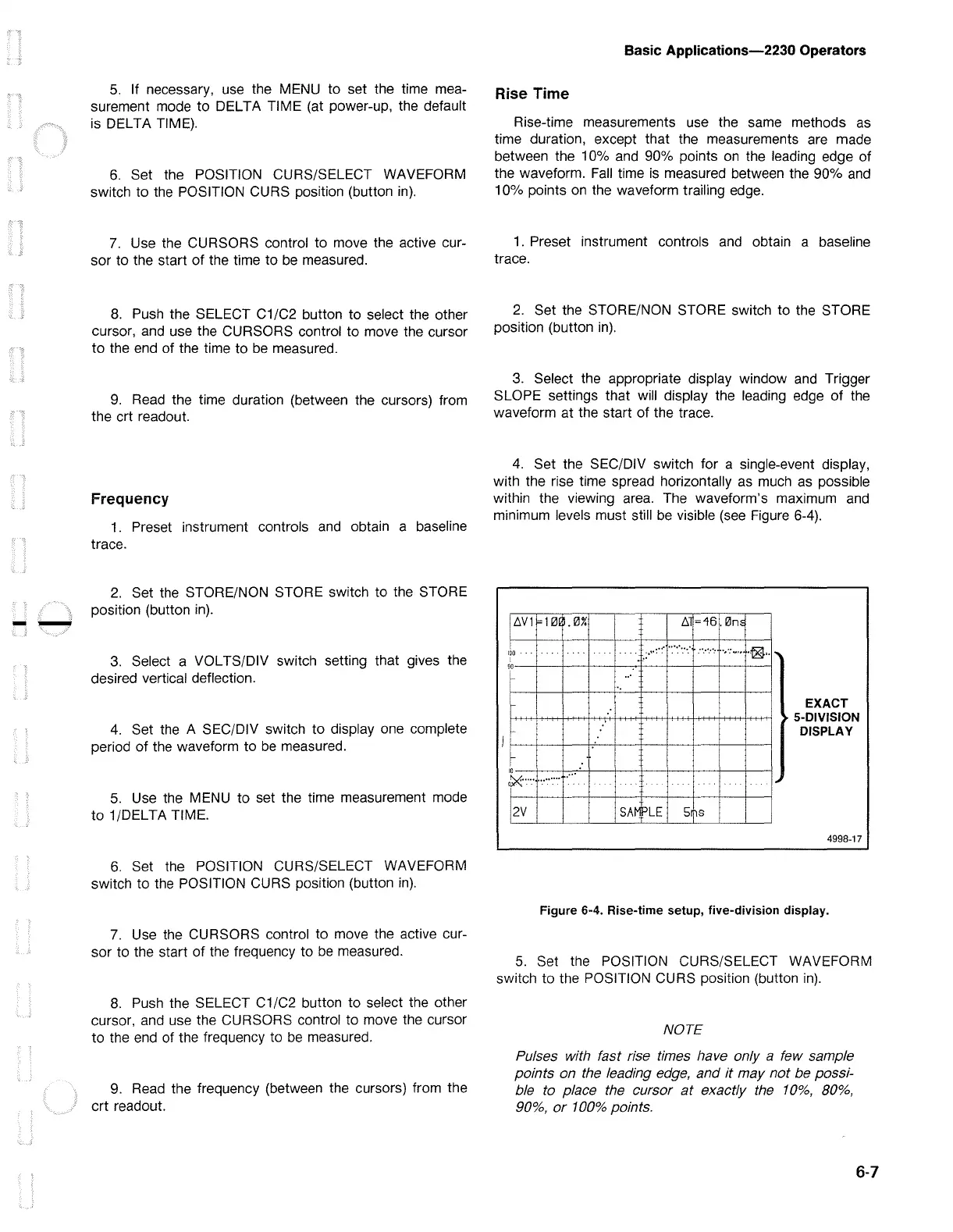
4.
Set the SEC/DIV switch for a single-event display,
with the rise time spread horizontally
as
much as possible
within the viewing area. The waveform's maximum and
minimum levels must still
be
visible (see Figure 6-4).
ti
V 1 = 1
0tl.
0%
ti
=46.0m
I
IOO
.:·":·:··:·:··:·.'
...........
·,·:
....
~
..
...
I
,o-+---+-+---+-+----+---l-----+---l-------a
EXACT
• 5-DIVISION
DISPLAY
\,___'
-+--1-----1--'--+----+--'--+---+-----+---'
~
..............
•:··
..
i
2V
I i
SA~LE
5hs
4998-17
Figure 6-4. Rise-time setup, five-division display.
5.
Set the POSITION CURS/SELECT WAVEFORM
switch to the POSITION CURS position (button
in).
NOTE
Pulses with fast rise times have only a few sample
points on the leading
edge,
and
it
may not be possi-
ble to place the cursor
at
exactly
the
10%,
80%,
90%,
or
100%
points.
6-7

 Loading...


