--
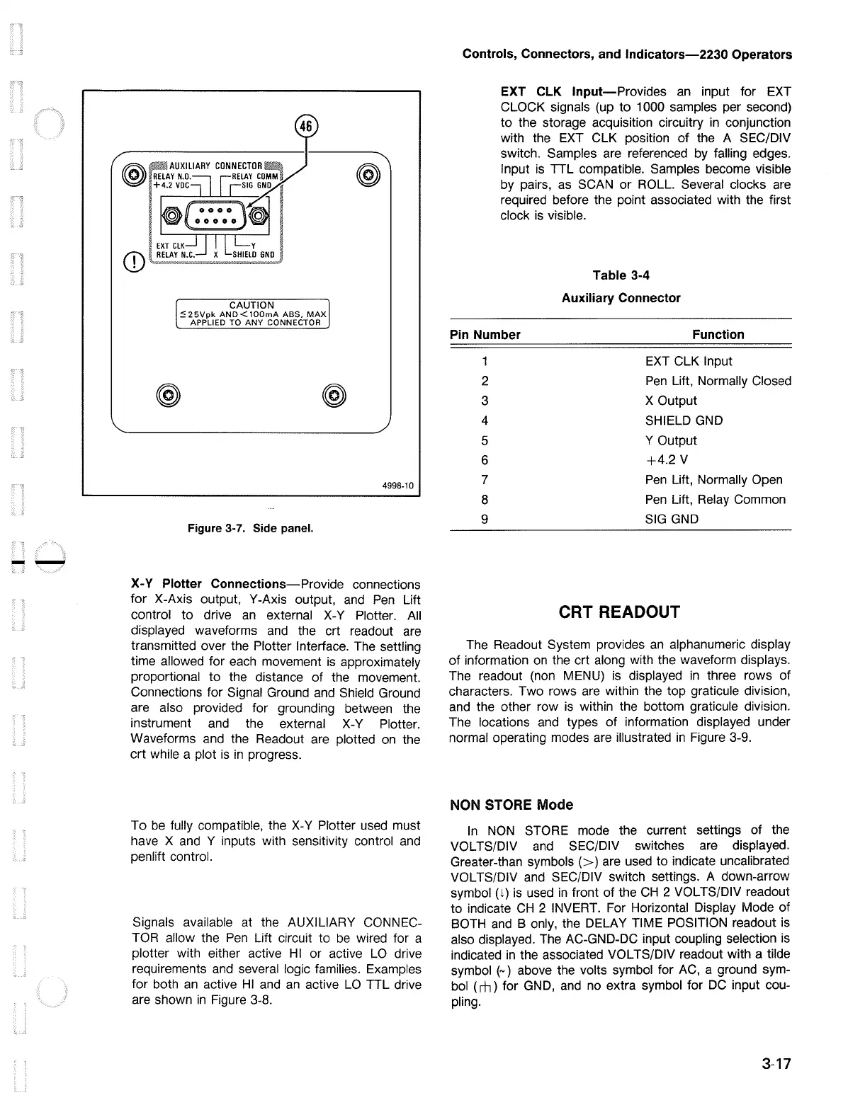
CAUTION
:':25Vpk
AND<lOOmA
ABS.
MAX
APPLIED TO
ANY
CONNECTOR
@
@
Figure 3-7. Side panel.
@
4998-10
X-Y Plotter
Connections-Provide
connections
for
X-Axis output, Y-Axis output, and
Pen
Lift
control
to
drive
an
external X-Y Plotter.
All
displayed waveforms and the crt readout are
transmitted over the Plotter Interface. The settling
time allowed for each movement is approximately
proportional to the distance
of
the movement.
Connections for Signal Ground and Shield Ground
are also provided for grounding between the
instrument and the external X-Y Plotter.
Waveforms and the Readout are plotted on the
crt
while a plot
is
in
progress.
To
be
fully compatible, the X-Y Plotter used must
have X and Y inputs with sensitivity control and
penlift control.
Signals available at the AUXILIARY CONNEC-
TOR allow the
Pen
Lift circuit to
be
wired for a
plotter with either active
HI
or active
LO
drive
requirements and several logic families. Examples
for both
an
active
HI
and
an
active
LO
TTL drive
are shown
in
Figure 3-8.
Controls, Connectors, and
lndicators-2230
Operators
EXT
CLK
Input-Provides
an
input for EXT
CLOCK signals (up to 1000 samples per second)
to
the storage acquisition circuitry
in
conjunction
with the EXT CLK position
of
the A SEC/DIV
switch. Samples are referenced by falling edges.
Input
is
TTL compatible. Samples become visible
by pairs,
as
SCAN
or
ROLL
Several clocks are
required before the point associated with the first
clock
is
visible.
Table 3-4
Auxiliary Connector
Pin
Number Function
1
2
3
4
5
6
7
8
9
EXT CLK Input
Pen
Lift, Normally Closed
X Output
SHIELD GND
Y Output
+4.2
V
Pen
Lift, Normally Open
Pen
Lift, Relay Common
SIG
GND
CRT READOUT
The Readout System provides
an
alphanumeric display
of
information on the crt along with the waveform displays.
The readout (non MENU) is displayed
in
three rows of
characters. Two rows are within the top graticule division,
and the other row
is
within the bottom graticule division.
The locations and types
of
information displayed under
normal operating modes are illustrated
in
Figure 3-9.
NON STORE Mode
In
NON
STORE mode the current settings
of
the
VOL TS/DIV and SEC/DIV switches are displayed.
Greater-than
symbols(>)
are used to indicate uncalibrated
VOL TS/DIV and SEC/DIV switch settings. A down-arrow
symbol (
1)
is used
in
front
of
the
CH
2 VOL TS/DIV readout
to indicate
CH
2 INVERT. For Horizontal Display Mode of
BOTH and B only, the DELAY TIME POSITION readout is
also displayed. The AC-GND-DC input coupling selection is
indicated
in
the associated VOL TS/DIV readout with a tilde
symbol
(~)
above the volts symbol for AC, a ground sym-
bol (
rh)
for GND, and no extra symbol for
DC
input cou-
pling.
3-17

 Loading...


