Controls, Connectors, and
lndicators-2230
Operators
In
Peak Detect mode, the minimum
and
maximum lev-
els of the input signal within the time represented by
1 /50 of a division unmagnified
(1
/25
of
a division
in
CHOP
or
ALT) are digitized
and
stored
in
acquisition
memory
as
a data pair. The displayed data points are
connected
by
vectors.
In
Sample mode, the signal
is
sampled at a rate that
produces 100 samples per graticule division.
In
RECORD sampling, the displayed sample points are
connected
by
either vectors or dots. For REPETITIVE
Storage mode, the sample points are displayed
as
dots.
ACCPEAK-Will cause displays to accumulate. The
largest maximum
and
smallest minimum sample
acquisitions
are
retained for each trigger-referenced
sample record over multiple acquisition cycles.
When
ACCPEAK
is
used with hardware peak detection
(50
µ,s
per division
to
0.1
s per division), updating of maximum
and minimum samples also occurs within each time-
base clock period. Changing any switch that affects the
acquisition parameters resets ACCPEAK displays.
ACCPEAK mode
is
valid for triggered acquisitions only
and
is
not operational
in
any mode that does not allow
triggers (see Table 3-2).
AVERAGE-ls
used for multiple record averaging.
Whenever AVERAGE
is
selected, SAMPLING
is
also
selected automatically.
When
on, a normalized algo-
rithm
is
used for continuous display of the signal at full
amplitude during the averaging process. Averaging
is
the default for REPETITIVE Store mode only. The
amplitude resolution increases with the number of
weighted acquisitions included
in
the display. The
number of weighted acquisitions included
in
the A VER-
AGE display is Menu selectable. The default weight of
AVERAGE mode
is
1
/4.
Other choices are Menu select-
able. The number of sweeps (SWP LIMIT) allowed to
occur before averaging stops
is
also Menu selectable.
REAR PANEL
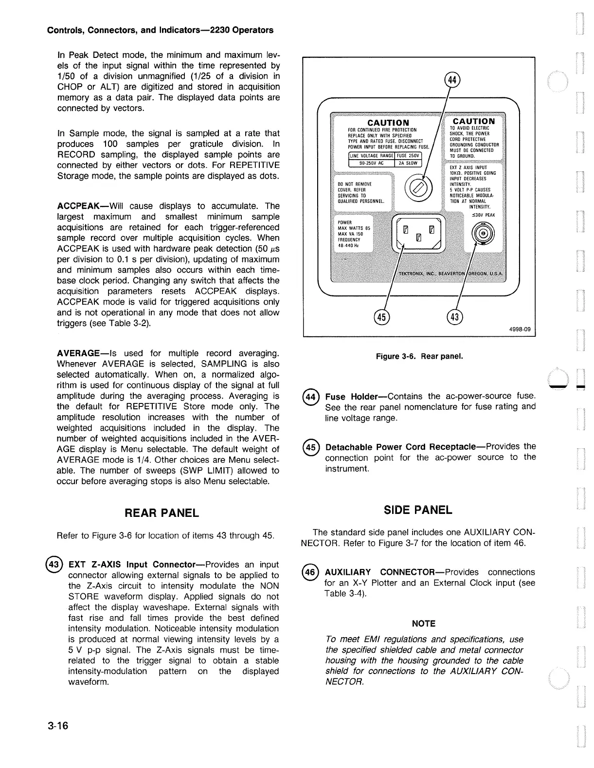
Refer to Figure 3-6 for location of items 43 through
45.
®
3-16
EXT Z-AXIS Input Connector-Provides
an
input
connector allowing external signals to
be
applied to
the Z-Axis circuit to intensity modulate the
NON
STORE waveform display. Applied signals do not
affect the display waveshape. External signals with
fast rise
and
fall
times provide the best defined
intensity modulation. Noticeable intensity modulation
is produced at normal viewing intensity levels
by
a
5 V p-p signal. The Z-Axis signals must
be
time-
related to the trigger signal to obtain a stable
intensity-modulation pattern
on
the displayed
waveform.
@
CAUTION
4998-09
Figure 3-6. Rear panel.
Fuse Holder-Contains the ac-power-source fuse.
See the rear panel nomenclature for fuse rating
and
line voltage range.
@ Detachable Power Cord Receptacle-Provides the
connection point for the ac-power source to the
instrument.
SIDE PANEL
The standard side panel includes
one
AUXILIARY CON-
NECTOR. Refer to Figure 3-7 for the location of item
46.
@ AUXILIARY CONNECTOR-Provides connections
for
an
X-Y Plotter
and
an
External Clock input (see
Table 3-4).
NOTE
To
meet EM/ regulations and specifications, use
the specified shielded cable and metal connector
housing with
the
housing grounded to the cable
shield for connections to the AUXILIARY
CON-
NECTOR.

 Loading...


