--
Section
4-2230
Operators
OPERATING CONSIDERATIONS
This part contains basic operating information
and
tech-
niques that should
be
considered before attempting to
make any measurements with the instrument.
GRATICULE
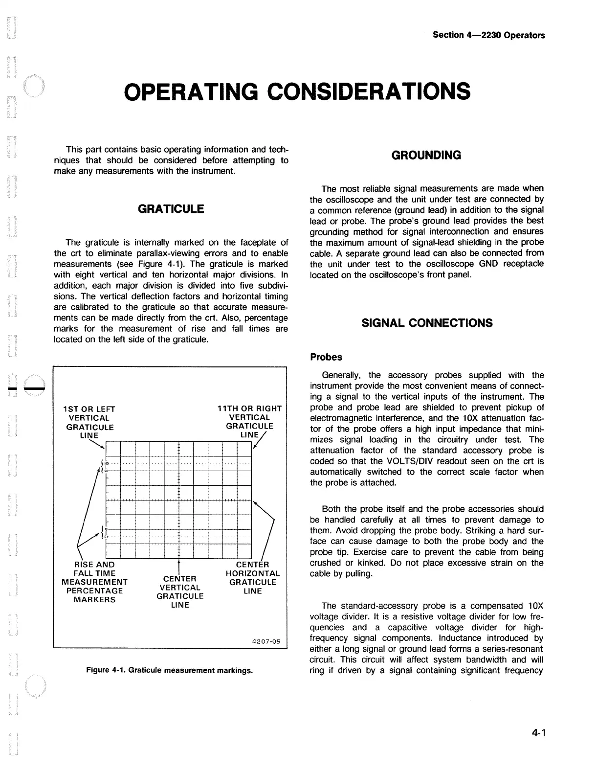
The graticule
is
internally marked
on
the faceplate of
the crt to eliminate parallax-viewing errors
and
to enable
measurements
(see
Figure
4-1
).
The graticule
is
marked
with eight vertical
and
ten horizontal major divisions.
In
addition,
each
major division
is
divided into five subdivi-
sions. The vertical deflection factors
and
horizontal timing
are calibrated to the graticule so that accurate measure-
ments
can
be
made directly from the crt. Also, percentage
marks for the measurement of rise
and
fall times
are
located
on
the left side of the graticule.
1ST
OR LEFT
VERTICAL
GRATICULE
LINE
"-.._
I
,oo
I
so
"
I
Ol·•
I
D
ME
RISE
AN
FALL
Tl
MEASUREMENT
PERCENTAGE
MARKERS
CENTER
VERTICAL
GRATICULE
LINE
11TH
OR
RIGHT
VERTICAL
GRATICULE
LIN/
I
CEN TER
H RIZ 0
ONTAL
GRATICULE
LINE
4207-09
Figure 4-1. Graticule measurement markings.
GROUNDING
The most reliable signal measurements
are
made when
the oscilloscope
and
the unit under test are connected by
a common reference (ground
lead)
in
addition to the signal
lead
or probe. The probe's ground
lead
provides the best
grounding method for signal interconnection
and
ensures
the maximum amount of signal-lead shielding in the probe
cable. A separate ground
lead
can also
be
connected from
the unit under test to the oscilloscope
GND
receptacle
located
on
the oscilloscope's front panel.
SIGNAL CONNECTIONS
Probes
Generally, the accessory probes supplied with the
instrument provide the most convenient
means
of
connect-
ing
a signal to the vertical inputs of the instrument.
The
probe
and
probe lead
are
shielded to prevent pickup of
electromagnetic interference,
and
the 1
OX
attenuation fac-
tor of the probe offers a
high
input impedance that mini-
mizes signal loading
in
the circuitry under test. The
attenuation factor of the standard accessory probe
is
coded so that the VOL TS/DIV readout
seen
on
the crt
is
automatically switched to the correct scale factor when
the probe
is
attached.
Both the probe itself
and
the probe accessories should
be
handled carefully at
all
times to prevent damage to
them. Avoid dropping the probe body. Striking a hard sur-
face
can
cause damage to both the probe body
and
the
probe tip. Exercise care to prevent the cable from being
crushed or kinked.
Do
not place excessive strain
on
the
cable
by
pulling.
The
standard-accessory probe
is
a compensated 1
OX
voltage divider. It
is
a resistive voltage divider for low fre-
quencies
and
a capacitive voltage divider for high-
frequency signal components. Inductance introduced
by
either a long signal or ground
lead
forms a series-resonant
circuit. This circuit will affect system bandwidth
and
will
ring if driven
by
a signal containing significant frequency
4-1

 Loading...


